Dodge Durango (HB). Manual - part 1118


  Index      Dodge     Dodge Durango (HB) - service repair manual 2005 year


Search            


Content   ..  1116  1117  1118  1119   ..


Dodge Durango (HB). Manual - part 1118


1. Before proceeding with this repair procedure review the required service warnings and precautions. (Refer to 13

- FRAME & BUMPERS/FRAME - WARNING)

2. Disconnect and isolate the battery negative cable.

3. Remove the front wheelhouse splash shield. (Refer to 23 - BODY/EXTERIOR/FRONT WHEELHOUSE SPLASH

SHIELD - REMOVAL)

4. Remove the front bumper. (Refer to 13 - FRAME & BUMPERS/BUMPERS/FRONT BUMPER - REMOVAL)

5. Remove the washer bottle, if required.

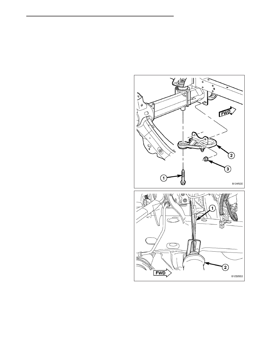
6. Remove the front cab mount bolt (1) to the Front

End Sheet Metal (FESM) bracket and the lower
bumper support nuts (3) attaching the tow hook (2),
if equipped.

CAUTION: Do not use any flame or plasma cutting
equipment to cut the frame in the next step. This
is due to the inaccurate nature of the cut-line and
the fact that the high temperatures achieved dur-
ing the flame or plasma cutting will change the
metal characteristics and may weaken the frame
and/or repair location.

7. Using a reciprocating saw (2) or equivalent, care-

fully cut and remove the damaged frame rail tip
behind the stop bracket (1).

HB

FRAME & BUMPERS

13 - 11

8. Remove the brake lines as necessary, to gain

access to the upper fillet welds. (Refer to 5 -
BRAKES/HYDRAULIC/MECHANICAL/BRAKE
LINES - REMOVAL)

9. For the right side rail tip, remove the oil filter to

gain access to the inner fillet weld.

10. Remove the four puddle welds attaching the

remaining frame tip section (2) to the frame (1) at
the locations indicated. (Right side shown, left
side similar.)

11. Using a plasma cutter, remove the welds (4) by

cutting along the outside edge of the weld (1)
approximately 1/8 in. (2).

12. With the puddle welds (1) removed, remove the

remaining piece of the frame tip (2) from within
the frame rail and discard.

13. Smooth and square the cut edges of the original

frame.

14. Remove any burrs at the holes (1) and frame

edges.

13 - 12

FRAME & BUMPERS

HB

15. Dry fit the new rail (2) to verify alignment, fit and

make any adjustments as necessary.

16. Remove all internal and external OEM e-coat

within 51 mm (2.0 in.) of the weld joint on the
replacement tip and the existing frame rail.

NOTE: Any burned surface coatings will need to be removed prior to application of corrosion preventative
coatings.

CAUTION: Shield the surrounding area and components from exposure to the welding spatter and heat.

17. Loosely install the lower FESM insulator and cab mounting bolt.

18. Position the stop bracket (2) against the frame rail

(1).

NOTE: If replacing the drivers’s side tip, the stop
bracket mounting tab will not be utilized. The stop
bracket may be rotated about the narrow end of
the trip and repositioned so interference of tab
with other parts is avoided. The mounting tab my
also be cut off.

NOTE: If replacing the passenger’s side tip, the
stop bracket mounting tab may be utilized if the
vehicle is equipped with optional rear AC system.

19. Using the appropriate measuring equipment, verify the front end sheet metal bracket’s location in all three (X,Y,

and Z) planes of space, and adjust if required. (Refer to 13 - FRAME & BUMPERS/FRAME - SPECIFICATIONS
- FRAME DIMENSION)

HB

FRAME & BUMPERS

13 - 13

CAUTION: Shield the surrounding area and com-
ponents from exposure to the welding spatter and
heat.

20. When correctly fitted, tack the three upper ring fil-

let welds (1) to hold the tip (3) in position, then
complete the ring fillet welds (1).

NOTE: Ring-fillet welds may be filled in with weld
material if an improved cosmetic appearance is
desired.

21. Confirm alignment of the replacement frame rail

tip.

22. Final welding should be performed in a skip

(stitch) type method to minimize the heat buildup
and frame distortion, utilizing the Weld Process
Specifications at the end of this section. The pre-
ferred method is GMAW (MIG). (Refer to 13 - FRAME & BUMPERS/FRAME - SPECIFICATIONS - WELDING)

a. Apply root pass welds to the root joint (5) behind the stop bracket (2), one quadrant at a time, switching to

the opposite side of the frame for each quadrant.

b. Apply root pass welds to the root joint in front (4) of the stop bracket (2), one quadrant at a time, switching

to the opposite side of the frame for each quadrant.

c. Clean the welds of any flux and other impurities before proceeding with the cover pass welds.

d. Apply the cover pass welds in the same manner as described above.

23. Confirm alignment of the replacement frame rail tip.

NOTE: Any burned surface coatings will need to be removed prior to application of corrosion preventative
coatings.

24. Dress the welded area and apply corrosion resistant coatings inside and out.

a. Apply etch-primer to the inside of the frame rail repair area.

b. Inside the rail, inject a creeping wax based rust inhibitor compound through the existing holes in the frame

ensuring 100% coverage including the space between the original frame rail and the reinforcing sleeve.

c. Apply a durable top coat to the outside of the repair area.

13 - 14

FRAME & BUMPERS

HB


Content   ..  1116  1117  1118  1119   ..