Content .. 1115 1116 1117 1118 ..
Dodge Durango (HB). Manual - part 1117
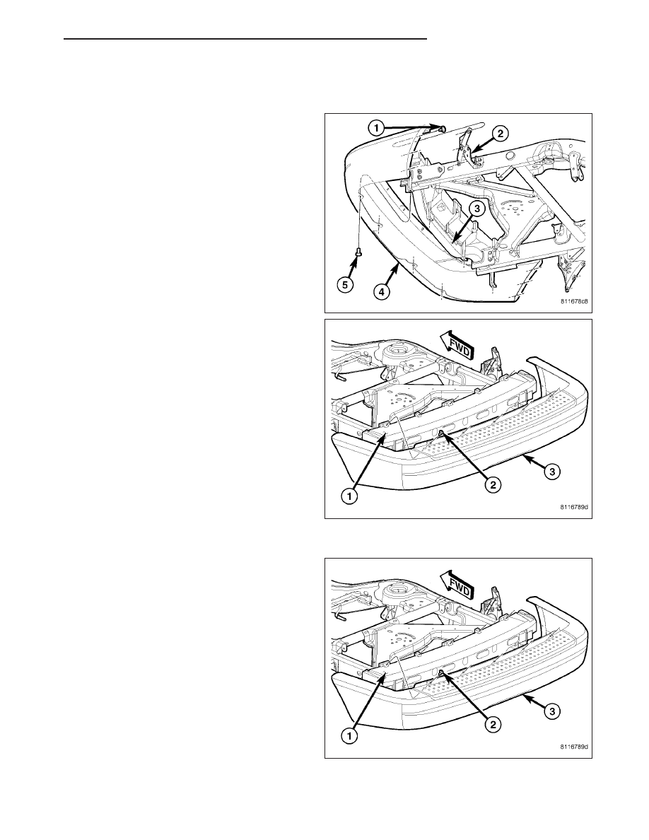
FASCIA-REAR
REMOVAL
1. Raise and support the vehicle.
2. Remove the screws (1) securing the fascia to the
support brackets (2).
3. Remove the lower push pin fasteners (5).
4. Open the liftgate and remove the upper push pin
fasteners (2).
5. Remove the fascia (3).
INSTALLATION
1. Position the fascia (3) and install the push pin fas-
teners (2).
HB
FRAME & BUMPERS
13 - 7