Dodge Durango (HB). Manual - part 1115


  Index      Dodge     Dodge Durango (HB) - service repair manual 2005 year


Search            


Content   ..  1113  1114  1115  1116   ..


Dodge Durango (HB). Manual - part 1115


REMOVAL

WARNING: IF TORCHES ARE USED WHEN WORK-
ING ON THE EXHAUST SYSTEM, WEAR PROTEC-
TIVE EYE COVERING AND DO NOT ALLOW THE
FLAME NEAR THE FUEL LINES.

CAUTION: When servicing or replacing exhaust
system components, be sure to disconnect all
oxygen sensor connectors. Allowing the exhaust
system to hang by the harness will damage the
wiring and/or sensor.

1. Raise and support the vehicle.

2. Saturate the bolts and nuts with Mopar

T

Rust Pen-

etrant. Allow 5 minutes for penetration.

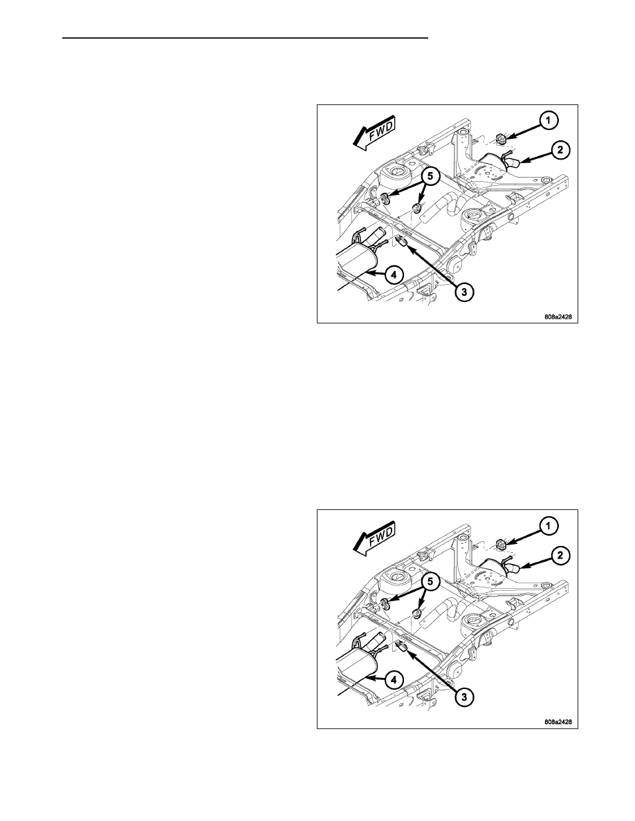
3. Remove the exhaust pipe-to-muffler clamp (3).

4. Grind any tack weld, if present.

5. Remove the exhaust pipe insulators (1).

6. Remove the rear muffler insulators (5) if necessary.

7. If necessary, heat connection with an oxygen/acet-

ylene torch and twist tailpipe out of muffler.

8. Remove the exhaust pipe (2) from the muffler (4).

INSPECTION

Discard rusted clamps, broken or worn supports and attaching parts. Replace a component with original equipment
parts, or equivalent. This will assure proper alignment with other parts in the system and provide acceptable
exhaust noise levels.

INSTALLATION

1. Remove any burrs from the exhaust pipe (2).

2. Connect the exhaust pipe (2) to the muffler (4).

3. Make sure that the alignment tang is seated in the

alignment slot.

4. Install the muffler-to-exhaust pipe clamp. Do not

tighten at thia time.

5. Install the rear muffler insulators (5), if removed.

6. Install the tail pipe insulators (1)

7. Check the exhaust system for contact with the

body panels. Make the necessary adjustments, if
necessary.

8. Tighten muffler-to-exhaust pipe clamp to 42 N·m

(31 ft. lbs.).

9. Lower the vehicle.

10. Start the engine, inspect for exhaust leaks. Repair

exhaust leaks as necessary.

HB

EXHAUST SYSTEM

11 - 9

FRAME & BUMPERS

TABLE OF CONTENTS

page

page

FRAME & BUMPERS

SPECIFICATIONS

TORQUE

. . . . . . . . . . . . . . . . . . . . . . . . . . . . . 1

FASCIA-FRONT

REMOVAL

. . . . . . . . . . . . . . . . . . . . . . . . . . . . . . 2

INSTALLATION

. . . . . . . . . . . . . . . . . . . . . . . . . . 3

SUPPORT-FRONT FASCIA

REMOVAL

. . . . . . . . . . . . . . . . . . . . . . . . . . . . . . 4

INSTALLATION

. . . . . . . . . . . . . . . . . . . . . . . . . . 5

BUMPER-FRONT

REMOVAL

. . . . . . . . . . . . . . . . . . . . . . . . . . . . . . 6

INSTALLATION

. . . . . . . . . . . . . . . . . . . . . . . . . . 6

FASCIA-REAR

REMOVAL

. . . . . . . . . . . . . . . . . . . . . . . . . . . . . . 7

INSTALLATION

. . . . . . . . . . . . . . . . . . . . . . . . . . 7

SUPPORT-REAR BUMPER

REMOVAL

. . . . . . . . . . . . . . . . . . . . . . . . . . . . . . 8

INSTALLATION

. . . . . . . . . . . . . . . . . . . . . . . . . . 8

BRACKET-REAR FASCIA

REMOVAL

. . . . . . . . . . . . . . . . . . . . . . . . . . . . . . 9

INSTALLATION

. . . . . . . . . . . . . . . . . . . . . . . . . . 9

FRAME

WARNING

SAFETY PRECAUTIONS AND WARNINGS

. . 10

STANDARD PROCEDURE

FRONT FRAME RAIL TIP REPLACEMENT

. . . 10

HYDROFORM FENDER RAIL REPAIR

. . . . . . 15

SPECIFICATIONS

WELD PROCESS

. . . . . . . . . . . . . . . . . . . . . 19

FRAME DIMENSIONS

. . . . . . . . . . . . . . . . . . 19

CROSSMEMBER-UNDERBODY

REMOVAL

. . . . . . . . . . . . . . . . . . . . . . . . . . . . . 21

INSTALLATION

. . . . . . . . . . . . . . . . . . . . . . . . . 22

HOOK-TOW

REMOVAL

. . . . . . . . . . . . . . . . . . . . . . . . . . . . . 22

INSTALLATION

. . . . . . . . . . . . . . . . . . . . . . . . . 23

SKID PLATE-FUEL TANK

REMOVAL

. . . . . . . . . . . . . . . . . . . . . . . . . . . . . 24

INSTALLATION

. . . . . . . . . . . . . . . . . . . . . . . . . 25

RECEIVER KIT-TRAILER TOW

REMOVAL

. . . . . . . . . . . . . . . . . . . . . . . . . . . . . 25

INSTALLATION

. . . . . . . . . . . . . . . . . . . . . . . . . 26

SKID PLATE-TRANSFER CASE

REMOVAL

. . . . . . . . . . . . . . . . . . . . . . . . . . . . . 27

INSTALLATION

. . . . . . . . . . . . . . . . . . . . . . . . . 27

FRAME & BUMPERS

SPECIFICATIONS

TORQUE

DESCRIPTION

N·m

Ft. Lbs.

In. Lbs.

Front bumper reinforcement nuts

109

80

Front cab mount bolt

81

60

Front crossmember bolts/nuts

102

75

Front tow hook bracket nuts

109

80

Front tow hook/bumper reinforcement nuts

109

80

Fuel tank skid plate bolts - inboard

41

30

Fuel tank skid plate bolts - outboard

37

27

Lower radiator crossmember bolts

28

21

Trailer hitch bolts/nuts

183

135

Transfer case skid plate bolts

23

17

HB

FRAME & BUMPERS

13 - 1

FASCIA-FRONT

REMOVAL

1. Remove the grille. (Refer to 23 - BODY/EXTERI-

OR/GRILLE - REMOVAL)

2. Remove the headlamps. (Refer to 8 - ELECTRI-

CAL/LAMPS/LIGHTING - EXTERIOR/HEADLAMP
UNIT - REMOVAL)

3. Remove the wheel well screws (1) and (2).

4. Release the upper tabs (1) and remove the fascia.

5. Remove the screws (4) and remove the air dam

(3).

13 - 2

FRAME & BUMPERS

HB


Content   ..  1113  1114  1115  1116   ..