Content .. 1009 1010 1011 1012 ..
Dodge Durango (HB). Manual - part 1011
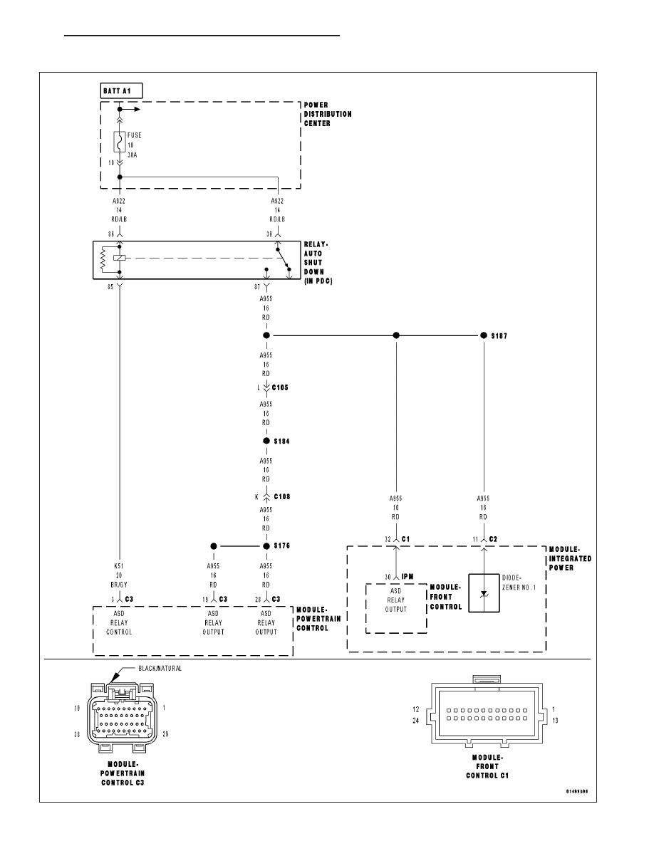
*ENGINE CRANKS BUT DOES NOT START
HB
ENGINE ELECTRICAL DIAGNOSTICS
9 - 1043
|
|
|
Content .. 1009 1010 1011 1012 ..
*ENGINE CRANKS BUT DOES NOT START HB ENGINE ELECTRICAL DIAGNOSTICS 9 - 1043 |