Dodge Durango (HB). Manual - part 42


  Index      Dodge     Dodge Durango (HB) - service repair manual 2005 year


Search            


Content   ..  40  41  42  43   ..


Dodge Durango (HB). Manual - part 42


7. Install bolts into two of the threaded holes in the

flange 180° apart.

8. Position Holder 6719 against the flange and install

a bolt and washer into one of the remaining
threaded holes. Tighten the bolts so the Holder
6719 is held to the flange.

9. Remove pinion nut and washer.

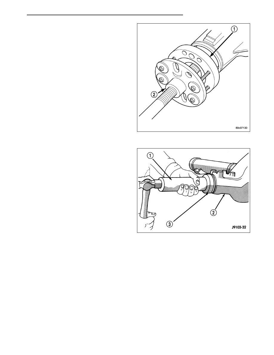
10. Remove flange (1) with Remover C-452 (2).

11. Remove pinion seal with a pry tool or slide-ham-

mer mounted screw.

INSTALLATION

1. Apply a light coating of gear lubricant on the lip of

pinion seal.

2. Install new pinion seal with Installer C-4076-B (3)

and Handle C-4735 (1).

HB

REAR AXLE - 8 1/4

3 - 95

3. Install flange on the end of the shaft with the refer-

ence marks aligned.

4. Install bolts into two of the threaded holes in the

flange 180° apart.

5. Position Holder 6719 against flange. Install a bolt

and washer into one of the remaining threaded
holes. Tighten bolts so Holder 6719 is held to the
flange.

6. Install flange on pinion shaft with Installer C-3718

and Holder 6719.

7. Install pinion washer and a new pinion nut. The

convex side of the washer must face outward.

CAUTION: Do not exceed the minimum tightening
torque

when

installing

the

companion

flange

retaining nut at this point. Failure to follow these
instructions can damage the collapsible spacer or
bearings.

8. Hold flange with Holder 6719 (2) and tighten pinion

nut to 285 N·m (210 ft. lbs.). Rotate pinion several
revolutions to ensure bearing rollers are seated.

9. Rotate pinion flange (1) with an inch pound torque

wrench (2). Rotating torque should be equal to the
reading recorded during removal plus an additional
0.56 N·m (5 in. lbs.).

CAUTION: Never loosen pinion nut to decrease
pinion bearing rotating torque and never exceed
specified preload torque. If rotating torque is
exceeded, a new collapsible spacer must be
installed. Failure to follow these instructions can
damage the collapsible spacer or bearings.

10. If rotating torque is low use Holder 6719, to hold

flange and tighten pinion nut in 6.8 N·m (5 ft. lbs.)
increments

until

proper

rotating

torque

is

achieved.

NOTE: The seal replacement is unacceptable if
final pinion nut torque is less than 285 N·m (210 ft.
lbs.).

NOTE: The bearing rotating torque should be con-
stant during a complete revolution of the pinion. If the rotating torque varies, this indicates a binding con-
dition.

11. Install propeller shaft.

12. Install rear brake rotors components.

3 - 96

REAR AXLE - 8 1/4

HB

DIFFERENTIAL

REMOVAL

1. Remove differential cover.

2. Remove axle shafts.

3. Remove ABS sensor from housing.

4. Mark differential housing and bearing caps (3) for

installation reference.

5. Remove bearing adjuster lock bolt (3) from bearing

caps.

6. Loosen differential bearing cap bolts.

7. Loosen differential bearing adjusters through the

axle tubes (1) with Wrench C-4164 (3).

8. Hold differential case while removing bearing caps

and adjusters.

9. Remove differential case and tag differential bear-

ing cups and adjusters to indicate location.

10. Clean housing cavity with flushing oil, light engine

oil or a lint free cloth.

NOTE: Do not use steam, kerosene or gasoline to
clean the housing.

HB

REAR AXLE - 8 1/4

3 - 97

DISASSEMBLY

1. Rotate one pinion gear (2) with thrust washer (3) to

the differential window (1). Remove gear and thrust
washer.

2. Rotate remaining pinion gear (3) with thrust washer

(2) to the differential window (1). Remove gear and
washer.

3. Remove differential side gears (1) (2) and thrust

washers.

3 - 98

REAR AXLE - 8 1/4

HB


Content   ..  40  41  42  43   ..