Dodge Durango (HB). Manual - part 40


  Index      Dodge     Dodge Durango (HB) - service repair manual 2005 year


Search            


Content   ..  38  39  40  41   ..


Dodge Durango (HB). Manual - part 40


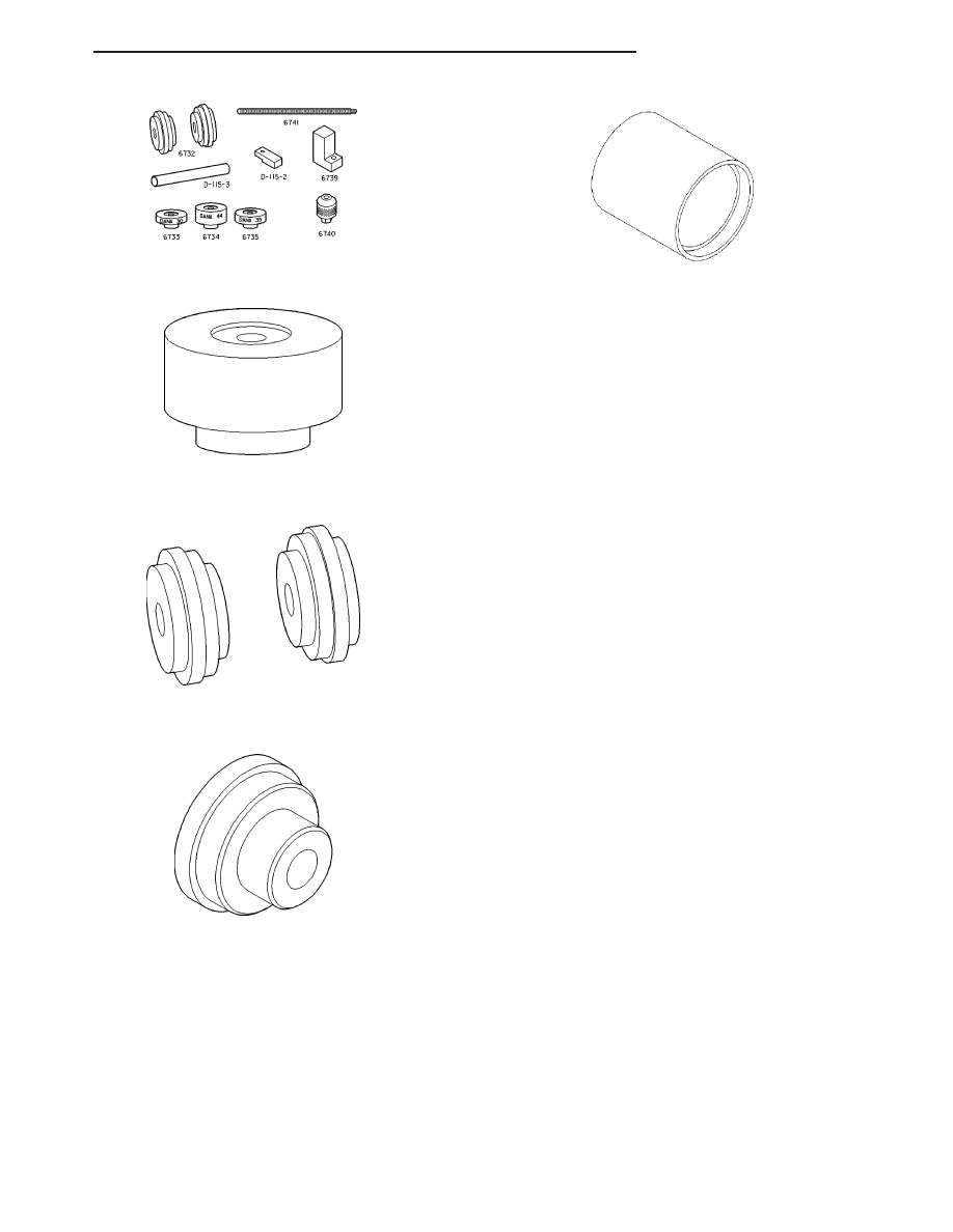
PINION GAUGE SET 6730/6774/6775

PINION BLOCK 8540

ARBOR DISCS 8541

INSTALLER 9337

RECEIVER 9338

HB

REAR AXLE - 8 1/4

3 - 87

COVER-DIFFERENTIAL

REMOVAL

1. Remove diffrential fill plug.

2. Remove watts link bell crank bolt (2) from differen-

tial cover (1).

3. Remove differential cover bolts.

4. Remove cover and drain fluid.

INSTALLATION

1. Clean differential cover.

2. Apply a bead of orange Mopar Axle RTV Sealant

(1) or equivalent to the cover (2).

CAUTION: If cover is not installed within 3 to 5
minutes, the cover must be cleaned and new RTV
applied. Failure to follow these instructions will
compromise adhesion quality.

3. Install cover and tighten bolts in a criss-cross pat-

tern to 44 N·m (32 ft. lbs.).

4. Fill differential with 2.07 L (4.375 pts.) of gear lubri-

cant.

CAUTION: Fill differential by volume only, not to
the bottom of fill plug. Failure to follow these
instructions will cause an over fill condition.

5. Install fill hole plug.

6. Install watts link bell crank bolt and tighten to 217 N·m (160 ft. lbs.).

NOTE: Bell crank bolt has a Loctite

T

patch, a new bolt should be used. If bolt is not available, clean bolt

and apply Loctite

T

242 to the threads.

3 - 88

REAR AXLE - 8 1/4

HB

SHAFT-AXLE

REMOVAL

1. With vehicle in neutral, position it on a hoist.

2. Remove brake caliper adapter with caliper and

remove rotor.

3. Remove differential housing cover and drain lubri-

cant.

4. Rotate differential case, to access pinion mate

shaft lock screw (4). Remove screw (4) and pinion
mate shaft (1) from differential case.

5. Push axle shaft (2) inward and remove axle shaft

C-lock (1).

6. Remove axle shaft.

HB

REAR AXLE - 8 1/4

3 - 89

INSTALLATION

1. Lubricate bearing bore and seal lip with gear lubri-

cant.

2. Insert axle shaft (1) through seal (2) and engage

into side gear splines.

3. Insert C-lock in end of axle shaft then push axle

shaft outward to seat C-lock in side gear.

4. Insert pinion shaft into differential case and through

thrust washers and differential pinions.

5. Align hole in shaft with hole in differential case and

install lock screw (4) with Loctite

T

on the threads.

Tighten lock screw to 25 N·m (220 in. lbs.).

6. Install differential cover and fill with gear lubricant.

7. Install brake rotor and caliper adapter with caliper.

3 - 90

REAR AXLE - 8 1/4

HB


Content   ..  38  39  40  41   ..