Dodge Durango (HB). Manual - part 18


  Index      Dodge     Dodge Durango (HB) - service repair manual 2005 year


Search            


Content   ..  16  17  18  19   ..


Dodge Durango (HB). Manual - part 18


INSTALLATION

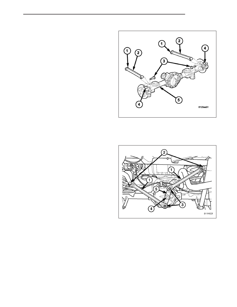
1. Install the upper control arm (2) to the vehicle.

2. Install the upper control arm bolt and flag nut (1) at

the frame.

3. Install the upper control arm bolt (3) and flag nut

(4) at the axle (5).

4. Lower the vehicle to the ground and then tighten

the bolts to 156 N·m (115 ft.lbs.).

BELL CRANK

REMOVAL

1. Raise and support the vehicle.

2. Remove the watts link nuts (3) at the bell crank (5).

3. Remove both watts links (1) from the bell crank (5).

4. Remove the bell crank bolt (4) from the differential

cover and remove the bell crank (5).

HB

REAR

2 - 39

INSTALLATION

1. Install the bell crank (5) and bolt (4) to the differen-

tial cover and tighten 251 N·m (185 ft.lbs).

2. Install the watts links (1) and nuts (3) to the bell

crank (5) and tighten 108 N·m (80 ft.lbs).

3. Lower the vehicle.

WATTS LINK

REMOVAL

1. Raise and support the vehicle.

2. Remove the upper nut (2) and bolt (2) to the watts

link at the frame.

3. Remove the lower nut (3) to the watts link at the

bell crank (5) and remove the watts link.

INSTALLATION

1. Install the watts link in position at the frame.

2. Install the watts link nut and bolt (2) at the frame

and tighten 169 N·m (125 ft.lbs).

3. Install the watts links nuts (3) to the bell crank (5)

and tighten 108 N·m (80 ft.lbs).

4. Lower the vehicle.

2 - 40

REAR

HB

DIFFERENTIAL & DRIVELINE

TABLE OF CONTENTS

page

page

PROPELLER SHAFT

. . . . . . . . . . . . . . . . . . . . . . 1

HALF SHAFT

. . . . . . . . . . . . . . . . . . . . . . . . . . . 20

FRONT AXLE - C205F

. . . . . . . . . . . . . . . . . . . . . 31

REAR AXLE - 8 1/4

. . . . . . . . . . . . . . . . . . . . . . . 71

REAR AXLE - 9 1/4

. . . . . . . . . . . . . . . . . . . . . . 110

PROPELLER SHAFT

TABLE OF CONTENTS

page

page

PROPELLER SHAFT

DIAGNOSIS AND TESTING

PROPELLER SHAFT

. . . . . . . . . . . . . . . . . . . . 1

STANDARD PROCEDURE

PROPELLER SHAFT ANGLE

. . . . . . . . . . . . . . 4

SPECIFICATIONS

. . . . . . . . . . . . . . . . . . . . . . . . 5

SPECIAL TOOLS

. . . . . . . . . . . . . . . . . . . . . . . . 6

SHAFT-PROPELLER FRONT

REMOVAL

. . . . . . . . . . . . . . . . . . . . . . . . . . . . . . 7

INSTALLATION

. . . . . . . . . . . . . . . . . . . . . . . . . . 8

SHAFT-PROPELLER REAR

REMOVAL

. . . . . . . . . . . . . . . . . . . . . . . . . . . . . . 9

INSTALLATION

. . . . . . . . . . . . . . . . . . . . . . . . . 10

UNIVERSAL JOINTS-SINGLE CARDAN

DISASSEMBLY

DISASSEMBLY - WITH SNAP RINGS

. . . . . . . 10

DISASSEMBLY - WITH INJECTED RINGS

. . . 12

ASSEMBLY

ASSEMBLY - WITH SNAP RINGS

. . . . . . . . . 14

ASSEMBLY - WITH INJECTED RINGS

. . . . . . 15

PROPELLER SHAFT

DIAGNOSIS AND TESTING

PROPELLER SHAFT

PROPELLER SHAFT VIBRATION

Out-of-round tires or wheels that are out of balance, will cause a low frequency vibration.

Driveline vibration can also caused by loose or damaged engine mounts.

Propeller shaft vibration increases with vehicle speed. A vibration that occurs at a specific speed range, is not usu-
ally caused by an out of balance propeller shaft. Defective universal joints or an incorrect propeller shaft angle are
usually the cause of such a vibration.

HB

DIFFERENTIAL & DRIVELINE

3 - 1

DRIVELINE VIBRATION

Drive Condition

Possible Cause

Correction

Propeller Shaft Noise

1) Undercoating or other foreign
material on shaft.

1) Clean exterior of shaft and wash
with solvent.

2) Loose U-joint clamp screws.

2) Install new clamps and screws
and tighten to proper torque.

3) Loose or bent U-joint yoke or
excessive runout.

3) Install new yoke.

4) Incorrect driveline angularity.

4) Measure and correct driveline
angles.

5) Rear spring center bolt not in
seat.

5) Loosen spring u-bolts and seat
center bolt.

6) Worn U-joint bearings.

6) Install new U-joint.

7) Propeller shaft damaged or out
of balance.

7) Installl new propeller shaft.

8) Broken rear spring.

8) Install new rear spring.

9) Excessive runout or unbalanced
condition.

9) Re-index propeller shaft, test,
and evaluate.

10) Excessive drive pinion gear
shaft runout.

10) Re-index propeller shaft and
evaluate.

11) Excessive axle yoke deflection.

11) Inspect and replace yoke if
necessary.

12) Excessive transfer case runout.

12) Inspect and repair as necessary.

Universal Joint Noise

1) Loose U-joint clamp screws.

1) Install new clamps and screws
and tighten to proper torque.

2) Lack of lubrication.

2) Replace as U-joints as
necessary.

PROPELLER SHAFT BALANCE

If propeller shaft is suspected of being out of balance,
use the following procedure.

NOTE: Indexing propeller shaft 180° relative to the
yoke may eliminate some vibrations.

1. Raise and support vehicle.

2. Clean all foreign material from the propeller shaft

and universal joints.

3. Inspect propeller shaft for missing balance weights,

broken welds and bent areas. If propeller shaft is
bent, it must be replaced.

4. Inspect universal joints for wear and properly

installed.

5. Check propeller shaft bolt torques.

6. Remove wheels and install lug nuts to retain brake

rotors.

7. Mark and number the shaft six inches from the pin-

ion yoke end at four positions 90° apart.

8. Run and accelerate vehicle until vibration occurs. Note the intensity and speed the vibration occurred. Stop the

engine.

3 - 2

PROPELLER SHAFT

HB


Content   ..  16  17  18  19   ..