Dodge Durango (HB). Manual - part 16


  Index      Dodge     Dodge Durango (HB) - service repair manual 2005 year


Search            


Content   ..  14  15  16  17   ..


Dodge Durango (HB). Manual - part 16


CAUTION: Suspension components with rubber/urethane bushings (except stabilizer bar) should be tight-
ened with the vehicle at normal ride height. It is important to have the springs supporting the weight of the
vehicle when the fasteners are torqued. If springs are not at their normal ride position, vehicle ride comfort
could be affected and premature bushing wear may occur.

DIAGNOSIS AND TESTING

SPRING AND SHOCK

A knocking or rattling noise from a shock absorber may be caused by movement between mounting bushings and
metal brackets or attaching components. These noises can usually be stopped by tightening the attaching nuts. If
the noise persists, inspect for damaged and worn bushings, and attaching components. Repair as necessary if any
of these conditions exist.

A squeaking noise from the shock absorber may be caused by the hydraulic valving and may be intermittent. This
condition is not repairable and the shock absorber must be replaced.

The shock absorbers are not refillable or adjustable. If a malfunction occurs, the shock absorber must be replaced.
To test a shock absorber, hold it in an upright position and force the piston in and out of the cylinder four or five
times. The action throughout each stroke should be smooth and even.

If the vehicle is used for severe, off-road operation, the springs should be examined periodically. Check for broken
colis. Refer to Spring and Shock Absorber Diagnosis chart for additional information.

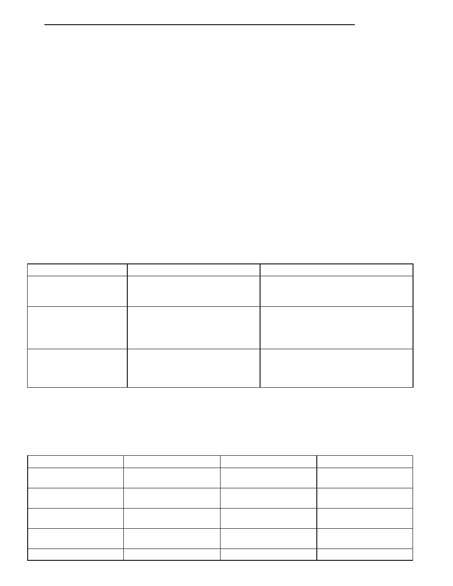
SPRING AND SHOCK ABSORBER

CONDITION

POSSIBLE CAUSES

CORRECTION

REAR OF VEHICLE SAGS

1. Broken coil spring.

1. Replace spring.

2. Spring fatigue.

2. Replace spring.

SPRING NOISE

1. Worn springs.

1. Replace spring.

2. Worn isolators.

2. Replace isolators.

3. Severly overloaded.

3. Check GVW of vehicle (Unload cargo).

SHOCK NOISE

1. Loose mounting fastener.

1. Tighten to specification.

2. Worn bushings.

2. Replace shock.

3. Leaking shock.

3. Replace shock.

SPECIFICATIONS

TORQUE CHART

TORQUE SPECIFICATIONS

DESCRIPTION

N·m

Ft. Lbs.

In. Lbs.

Shock Absorber

Lower Nut

102

75

Shock Absorber

Upper Bolt

102

75

Stabilizer Retainer to the

Axle

61

45

Stabilizer Link to Stabilizer

Bar

102

75

Stabilizer Link to Frame

102

75

HB

REAR

2 - 31

DESCRIPTION

N·m

Ft. Lbs.

In. Lbs.

Bell Crank to Differential

Bolt

251

185

Watts Link to Bell Crank

108

80

Watts Lateral Link to

Frame

169

125

Lower Control Arm

244

180

Upper Control Arm

156

115

JOUNCE BUMPER

REMOVAL

1. Raise and support the vehicle.

NOTE: Rocking motion may be required while pull-
ing the jounce bumper from the seating bracket

2. Twist and pull out the jounce bumper to remove the

jounce bumper from the seating bracket.

INSTALLATION

1. Install the jounce bumper and twist to seat in the

bracket.

2. Remove the support and lower the vehicle.

2 - 32

REAR

HB

SHOCK ABSORBER

REMOVAL

1. Raise vehicle and support the axle.

2. Lower the spare tire This step must be done if replacing the left side shock.

3. Remove the upper shock bolt and flag nut.

4. Remove the lower shock bolt and nut.

5. Remove the rear shock absorber from the vehicle.

INSTALLATION

1. Position the shock absorber in the brackets.

2. Install the bolts through the brackets and the shock. Install the flag nut on the top bolt and nut on lower bolt.

3. Tighten the upper and lower bolt/nuts Tighten to 102 N.m (75 ft. lbs.)

4. Raise the spare tire back in place if lowered for the left shock.

5. Remove the support and lower the vehicle.

SPRING-REAR-COIL

REMOVAL

1. Raise and support the vehicle.

2. Support the axle with a suitable holding fixture.

3. Remove the lower shock bolt.

4. Remove the bell crank bolt (4) to the rear axle.

5. Lower the jack to remove the spring and isolator

from the vehicle.

HB

REAR

2 - 33

INSTALLATION

NOTE: All torques should be made with the full
vehicle weight on the ground being supported by
the tires.

1. Position spring (3) to the vehicle on top of the iso-

lator (2).

2. Align the springs (3) to the spring pockets.

3. Raise the rear axle into place.

4. Install the bell crank bolt (4) to the rear axle.

Tighten to 251 N·m (185 ft. lbs.).

5. Install the lower shock bolts to the rear axle.

Tighten to 102 N·m (75 ft. lbs.).

6. Remove the holding fixture for the rear axle.

STABILIZER LINK

REMOVAL

1. Raise and support the vehicle.

2. Remove the rear tire.

3. Support the rear axle with a jack.

4. Remove the fuel tank skid plate (Refer to 13 -

FRAME & BUMPERS/FRAME/FUEL TANK SKID
PLATE - REMOVAL). This step must be done for
replacement of the left side stabilizer link.

5. Remove the rear fuel tank strap bolt and let the

strap (3) hang. This step must be done for
replacement of the left side stabilizer link.

6.

Push the fuel tank (2) over towards the driveshaft

(3) and install a block of wood (5) between the
frame (6) and the fuel tank (2) to allow for clear-
ance of the upper stabilizer link bolt (1) This step
must be done for replacement of the left side
stabilizer link.

2 - 34

REAR

HB


Content   ..  14  15  16  17   ..