Dodge Durango (HB). Manual - part 14


  Index      Dodge     Dodge Durango (HB) - service repair manual 2005 year


Search            


Content   ..  12  13  14  15   ..


Dodge Durango (HB). Manual - part 14


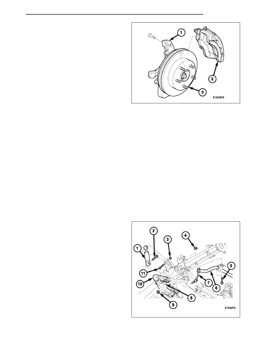
12. Install the disc brake caliper and adaptor assem-

bly (2) and tighten to 135 N·m (100 ft. lbs.) (Refer
to 5 - BRAKES/HYDRAULIC/MECHANICAL/DISC
BRAKE CALIPERS - INSTALLATION).

13. Install the wheel and tire assembly, (Refer to 22 -

TIRES/WHEELS/WHEELS - STANDARD PROCE-
DURE).

14. Remove the support and lower the vehicle.

15. Adjust the front suspension height and perform a

wheel alignment (Refer to 2 - SUSPENSION/
WHEEL

ALIGNMENT

-

STANDARD

PROCEDURE).

SHOCK ABSORBER

DIAGNOSIS AND TESTING

SHOCK

A knocking or rattling noise from a shock absorber may be caused by movement between mounting bushings and
metal brackets or attaching components. These noises can usually be stopped by tightening the attaching nuts. If
the noise persists, inspect for damaged and worn bushings, and attaching components. Repair as necessary if any
of these conditions exist.

A squeaking noise from the shock absorber may be caused by the hydraulic valving and may be intermittent. This
condition is not repairable and the shock absorber must be replaced.

The shock absorbers are not refillable or adjustable. If a malfunction occurs, the shock absorber must be replaced.
To test a shock absorber, hold it in an upright position and force the piston in and out of the cylinder four or five
times. The action throughout each stroke should be smooth and even.

The shock absorber bushings do not require any type of lubrication. Do not attempt to stop bushing noise by lubri-
cating them. Grease and mineral oil-base lubricants will deteriorate the bushing.

REMOVAL

1. Raise and support the vehicle.

2. Remove the tire and wheel assembly.

3. Support the lower control arm outboard end.

4. Remove the upper shock bolt (11) and nut (3).

5. Remove the stabilizer link (7) lower nut and then

separate the stabilizer link from the lower control
arm to gain access to the lower shock bolt (2)
(Refer to 2 - SUSPENSION/FRONT/STABILIZER
LINK - REMOVAL).

6. Remove the lower shock bolt (2).

7. Remove the shock (1).

HB

FRONT

2 - 23

INSTALLATION

1. Install the upper part of the shock (1) into the

frame bracket.

2. Install the nut (3) and bolt (11). Tighten to 102 N·m

(75 ft. lbs.).

3. Install the lower part of the shock (1) into the lower

control arm and Tighten the bolt (2) to 81 N·m (60
ft. lbs.).

4. Install the stabilizer link (7) lower nut to the lower

control arm (Refer to 2 - SUSPENSION/FRONT/
STABILIZER LINK - INSTALLATION).

5. Remove the support from the lower control arm

outboard end.

6. Install the tire and wheel assembly (Refer to 22 -

TIRES/WHEELS/WHEELS - STANDARD PROCE-
DURE).

7. Remove the support and lower the vehicle.

STABILIZER BAR

DESCRIPTION

The bar extends across the front underside of the
chassis and connects to the frame crossmember. The
ends of the bar mount to the lower suspension arm.
All mounting points of the stabilizer bar are isolated by
bushings.

OPERATION

The stabilizer bar is used to minimize vehicle front sway during turns. The bar helps to maintain a flat attitude to the
road surface.

2 - 24

FRONT

HB

REMOVAL

NOTE: To service the stabilizer bar the vehicle
should be on a drive on hoist. The vehicle suspen-
sion must be at curb height for stabilizer bar
installation.

1. Remove the stabilizer link upper nut and remove

the retainers and grommets (Refer to 2 - SUSPEN-
SION/FRONT/STABILIZER LINK - REMOVAL).

2. Remove the stabilizer bar retainer bolts (5) and

nuts (4) also remove the retainers (5) from the
frame sway bar and remove the bar (6).

3. If necessary, remove the bushings from the stabi-

lizer bar.

INSTALLATION

NOTE: To service the stabilizer bar the vehicle
must be on a drive on hoist. The vehicle suspen-
sion must be at curb height for stabilizer bar
installation.

1. If removed, install the bushings on the stabilizer

bar.

2. Position the stabilizer bar (6) on the frame cross-

member brackets and install the bracket and bolts
(5) finger-tight.

NOTE: Check the alignment of the bar to ensure
there is no interference with the either frame rail
or chassis component. Spacing should be equal
on both sides.

3. Install the stabilizer bar (6) to the stabilizer link (7)

and install the grommets and retainers and tighten
to 61 N·m (45 ft. lbs.).

4. Tighten the brackets to the frame and tighten to 61N·m (45 ft. lbs.).

5. Install the nuts to the stabilizer link and tighten to 169 N·m (125 ft. lbs.) (Refer to 2 - SUSPENSION/FRONT/

STABILIZER LINK - INSTALLATION).

HB

FRONT

2 - 25

STABILIZER LINK

REMOVAL

1. Raise and support the vehicle.

2. Remove the lower nut (9).

3. Remove the upper nut, retainers and grommets

from the stabilizer bar.

4. Remove the stabilizer link (7) from the vehicle.

INSTALLATION

1. Install the stabilizer link (7) to the vehicle.

2. Install the retainers, grommets and upper nut to the

stabilizer bar (6) and Tighten to 61 N·m (45 ft. lbs.).

3. Install the lower nut and Tighten to 169 N·m (125

ft. lbs.).

4. Remove the support and lower the vehicle.

BAR-TORSION

DESCRIPTION

The front of the bar connects to the back side of the lower suspension arm. The rear end of the bar is mounted in
a anchor that rests in the frame crossmember.

OPERATION

The torsion bars are used to control ride height and ride quality. The vehicle height is adjusted through an anchor
adjustment bolt that increases or decreases the wind up of the torsion bar. Increasing or decreasing the bar angle
changes the wind up of the suspension arms.

2 - 26

FRONT

HB


Content   ..  12  13  14  15   ..