Dodge Durango (HB). Manual - part 15


  Index      Dodge     Dodge Durango (HB) - service repair manual 2005 year


Search            


Content   ..  13  14  15  16   ..


Dodge Durango (HB). Manual - part 15


REMOVAL

CAUTION: The left and right side torsion bars are
NOT interchangeable. The bars are identified and
stamped R or L, for right or left. The bars do not
have a front or rear end and can be installed with
either end facing forward.

1. Raise and support the vehicle with the front sus-

pension hanging.

2. Remove the transfer case skid plate (Refer to 13 -

FRAME & BUMPERS/FRAME/TRANSFER CASE
SKID PLATE - REMOVAL).

NOTE: Count and record the number of turns for
installation reference.

3. Mark the adjustment bolt setting.

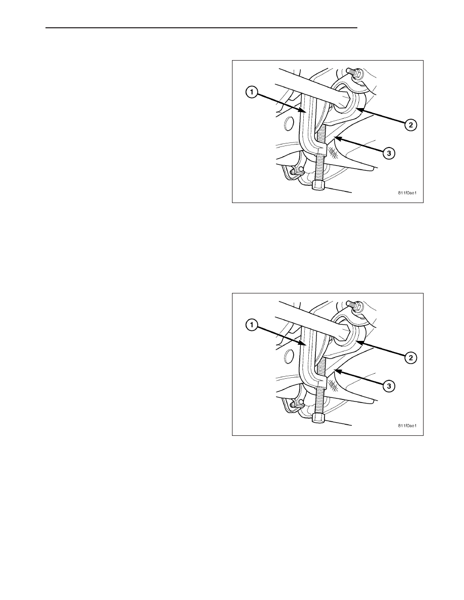
4. Install Special Tool - 8686 (1) to the anchor arm (2) and the cross member (3).

5. Increase the tension on the anchor arm tool 8686 (1) until the load is removed from the adjustment bolt and the

adjuster nut.

6. Turn the adjustment bolt counterclockwise to remove the bolt and the adjuster nut..

7. Remove the Special Tool - 8686 (1) , allowing the torsion bar to unload.

INSTALLATION

CAUTION: The left and right side torsion bars are
NOT interchangeable. The bars are identified and
stamped R or L, for right or left. The bars do not
have a front or rear end and can be installed with
either end facing forward.

1. Insert torsion bar ends into anchor and suspension

arm.

2. Position the anchor (2) in the crossmember frame

(3).

3. Install Special Tool - 8686 (1) to the anchor (2) and

the crossmember (3).

4. Increase the tension on the anchor in order to load

the torsion bar.

5. Install the adjustment bolt and the adjuster nut.

6. Turn adjustment bolt clockwise the recorded amount of turns.

7. Remove tool - 8686 (1)from the torsion bar crossmember (3).

8. Install the transfer case skid plate (Refer to 13 - FRAME & BUMPERS/FRAME/TRANSFER CASE SKID PLATE

- INSTALLATION).

9. Lower vehicle and adjust the front suspension height (Refer to 2 - SUSPENSION/WHEEL ALIGNMENT - STAN-

DARD PROCEDURE).

10. Perform a wheel alignment (Refer to 2 - SUSPENSION/WHEEL ALIGNMENT - STANDARD PROCEDURE).

HB

FRONT

2 - 27

BALL JOINT-UPPER

DIAGNOSIS AND TESTING

UPPER BALL JOINT

1. Raise the front of the vehicle. Place safety floor

stands under both lower control arms as far out-
board as possible. Lower the vehicle to allow the
stands to support some or all of the vehicle weight.

2. Remove the front tires.

3. Mount a dial indicator (1) solidly to the frame and

then zero the dial indicator.

4. Position dial indicator plunger on the topside of the

upper ball joint (5).

NOTE: The dial indicator plunger must be perpen-
dicular to the machined surface of the ball joint.

NOTE: Use care not to pry or tear the ball joint
boot, when checking the free play.

5. Position a pry bar (3) between the steering knuckle (4) and the upper control arm (2). Pry upwards on the upper

control arm.

6. If the travel exceeds 0.5 mm (0.020 in.), replace the upper control arm since the upper ball joint is integral to the

arm (Refer to 2 - SUSPENSION/FRONT/UPPER CONTROL ARM - REMOVAL).

7. If the upper ball joint is within specs reinstall the front tires (Refer to 22 - TIRES/WHEELS/WHEELS - STAN-

DARD PROCEDURE).

CONTROL ARM-UPPER

REMOVAL

1. Raise and support vehicle.

2. Remove wheel and tire assembly.

3. Remove the nut from upper ball joint.

4. Separate upper ball joint (1) from the steering

knuckle (3) with Remover 8677 (2).

CAUTION: When installing Remover 8677 (2) to
separate the ball joint, be careful not to damage
the ball joint seal.

2 - 28

FRONT

HB

5. Remove the control arm pivot bolts (1&2) and

remove control arm (3).

INSTALLATION

1. Position the control arm (3) into the frame brackets

(1&2). Install bolts and tighten to 102 N·m (75 ft.
lbs.).

2. Insert ball joint in steering knuckle and tighten ball joint nut to 75 N·m (55 ft. lbs.).

3. Install the wheel and tire assembly, (Refer to 22 - TIRES/WHEELS/WHEELS - STANDARD PROCEDURE).

4. Remove the support and lower vehicle.

5. Perform a wheel alignment, (Refer to 2 - SUSPENSION/WHEEL ALIGNMENT - STANDARD PROCEDURE).

HB

FRONT

2 - 29

REAR

TABLE OF CONTENTS

page

page

REAR

DESCRIPTION

. . . . . . . . . . . . . . . . . . . . . . . . . 30

DIAGNOSIS AND TESTING

SPRING AND SHOCK

. . . . . . . . . . . . . . . . . . 31

SPECIFICATIONS

TORQUE CHART

. . . . . . . . . . . . . . . . . . . . . . 31

JOUNCE BUMPER

REMOVAL

. . . . . . . . . . . . . . . . . . . . . . . . . . . . . 32

INSTALLATION

. . . . . . . . . . . . . . . . . . . . . . . . . 32

SHOCK ABSORBER

REMOVAL

. . . . . . . . . . . . . . . . . . . . . . . . . . . . . 33

INSTALLATION

. . . . . . . . . . . . . . . . . . . . . . . . . 33

SPRING-REAR-COIL

REMOVAL

. . . . . . . . . . . . . . . . . . . . . . . . . . . . . 33

INSTALLATION

. . . . . . . . . . . . . . . . . . . . . . . . . 34

STABILIZER LINK

REMOVAL

. . . . . . . . . . . . . . . . . . . . . . . . . . . . . 34

INSTALLATION

. . . . . . . . . . . . . . . . . . . . . . . . . 35

STABILIZER BAR

DESCRIPTION

. . . . . . . . . . . . . . . . . . . . . . . . . 36

OPERATION

. . . . . . . . . . . . . . . . . . . . . . . . . . . 36

REMOVAL

. . . . . . . . . . . . . . . . . . . . . . . . . . . . . 36

INSTALLATION

. . . . . . . . . . . . . . . . . . . . . . . . . 36

CONTROL ARM-LOWER

REMOVAL

. . . . . . . . . . . . . . . . . . . . . . . . . . . . . 37

INSTALLATION

. . . . . . . . . . . . . . . . . . . . . . . . . 37

CONTROL ARM-UPPER

REMOVAL

. . . . . . . . . . . . . . . . . . . . . . . . . . . . . 38

INSTALLATION

. . . . . . . . . . . . . . . . . . . . . . . . . 39

BELL CRANK

REMOVAL

. . . . . . . . . . . . . . . . . . . . . . . . . . . . . 39

INSTALLATION

. . . . . . . . . . . . . . . . . . . . . . . . . 40

WATTS LINK

REMOVAL

. . . . . . . . . . . . . . . . . . . . . . . . . . . . . 40

INSTALLATION

. . . . . . . . . . . . . . . . . . . . . . . . . 40

REAR

DESCRIPTION

The rear suspension is comprised of:

Shock Absorbers

Jounce Bumpers

Stabilizer Bar

Stabilizer links

Coil Springs

Watts Links (1)

Bell Crank (5)

Upper Control Arms

Lower Control Arms

Drive Axle

CAUTION: A vehicle should always be loaded so
the vehicle weight center-line is located immedi-
ately forward of the rear axle. Correct vehicle load-
ing provides proper front tire-to-road contact. This results in maximum vehicle handling stability and safety.
Incorrect vehicle weight distribution can cause excessive tire tread wear, spring fatigue or failure, and
erratic steering.

2 - 30

REAR

HB


Content   ..  13  14  15  16   ..