Dodge Durango (HB). Manual - part 13
7. Install the brake caliper and rotor (Refer to 5 - BRAKES/HYDRAULIC/MECHANICAL/ROTORS - INSTALLA-
TION).
8. Install the tire and wheel assembly (Refer to 22 - TIRES/WHEELS/WHEELS - STANDARD PROCEDURE).
9. Check the vehicle ride height (Refer to 2 - SUSPENSION/WHEEL ALIGNMENT - STANDARD PROCEDURE).
10. Perform a wheel alignment (Refer to 2 - SUSPENSION/WHEEL ALIGNMENT - STANDARD PROCEDURE).
CONTROL ARM-LOWER
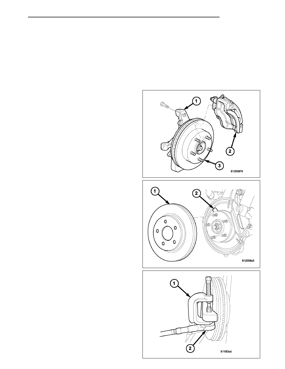
REMOVAL
1. Raise and support the vehicle.
2. Remove the wheel and tire assembly.
3. Remove the disc brake caliper assembly (2) (Refer
to 5 - BRAKES/HYDRAULIC/MECHANICAL/DISC
BRAKE CALIPERS - REMOVAL).
4. Remove the disc brake rotor (1) (Refer to 5 -
BRAKES/HYDRAULIC/MECHANICAL/ROTORS
-
REMOVAL).
5. Disconnect the wheel speed sensor at the wheel
well.
6. Disconnect the tie rod (2) from the knuckle using
special tool 8677 (1) (Refer to 19 - STEERING/
LINKAGE/TIE ROD END - REMOVAL).
HB
FRONT
2 - 19