Dodge Durango (HB). Manual - part 12


  Index      Dodge     Dodge Durango (HB) - service repair manual 2005 year


Search            


Content   ..  10  11  12  13   ..


Dodge Durango (HB). Manual - part 12


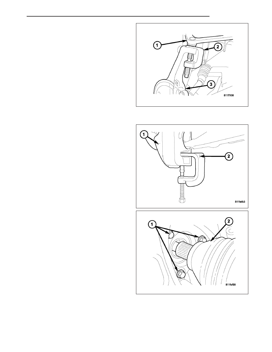
6. Remove the upper ball joint nut. Separate the ball

joint (1) from the knuckle (3) with Remover 8677
(2).

7. Install an hydraulic jack to support the lower control arm.

8. Remove the lower ball joint nut. Separate the ball

joint from the knuckle (1) with Remover 8677 (2)
and remove the knuckle.

9. Remove the hub/bearing bolts (1) from the knuckle.

HB

FRONT

2 - 15

10. Remove the hub/bearing (4) from the steering

knuckle (1) (Refer to 2 - SUSPENSION/FRONT/
HUB / BEARING - REMOVAL).

11. Remove the steering knuckle (1).

INSTALLATION

CAUTION: The ball joint stud tapers must be
CLEAN and DRY before installing the knuckle.
Clean the stud tapers with mineral spirits to
remove dirt and grease.

1. Install the hub/bearing to the steering knuckle and

tighten the bolts (1) to 163 N·m (120 ft. lbs.).

2. Install the knuckle (1) onto the upper and lower ball

joints.

3. Install the upper ball joint nut. Tighten the nut to 75

N·m (55 ft. lbs.).

4. Install the lower ball joint nut (3). Tighten the nut to

95 N·m (70 ft. lbs.).

5. Remove the hydraulic jack from the lower suspen-

sion arm (2).

6. Install the tie rod end and tighten the nut to 75 N·m (55 ft. lbs.).

2 - 16

FRONT

HB

7. Install the front halfshaft (2) into the hub/bearing

4X4 only.

8. Install the the halfshaft nut and tighten to 251 N·m

(185 ft. lbs.) 4X4 only.

9. Install the ABS wheel speed sensor if equipped

(Refer

to

5

-

BRAKES/ELECTRICAL/FRONT

WHEEL SPEED SENSOR - INSTALLATION) and
brake shield, rotor and caliper (Refer to 5 -
BRAKES/HYDRAULIC/MECHANICAL/ROTORS

-

INSTALLATION).

10. Install the wheel and tire assembly (Refer to 22 -

TIRES/WHEELS/WHEELS - STANDARD PROCE-
DURE).

11. Remove the support and lower the vehicle.

12. Perform a wheel alignment (Refer to 2 - SUS-

PENSION/WHEEL ALIGNMENT - STANDARD PROCEDURE).

BALL JOINT-LOWER

DIAGNOSIS AND TESTING

LOWER BALL JOINT

NOTE: If the ball joint is equipped with a lubrication fitting, grease the joint then road test the vehicle before
performing test.

1. Raise the front of the vehicle. Place safety floor stands under both lower control arms as far outboard as pos-

sible. Lower the vehicle to allow the stands to support some or all of the vehicle weight.

2. Mount a dial indicator solidly to the topside of the lower control arm and then zero the dial indicator.

3. Position the indicator plunger against the bottom surface of the steering knuckle.

NOTE: The dial indicator plunger must be perpendicular to the machined surface of the steering knuckle.

4. Position a pry bar under the tire assembly. Pry upwards on the tire assembly.

5. If the travel exceeds 0.5 mm (0.020 in.), replace the lower ball joint (Refer to 2 - SUSPENSION/FRONT/LOWER

BALL JOINT - REMOVAL).

REMOVAL

1. Remove the tire and wheel assembly.

2. Remove the brake caliper and rotor (Refer to 5 -

BRAKES/HYDRAULIC/MECHANICAL/ROTORS

-

REMOVAL).

3. Disconnect the tie rod (1) from the steering knuckle

using special tool 8677 (1) (Refer to 19 - STEER-
ING/LINKAGE/TIE ROD END - REMOVAL).

HB

FRONT

2 - 17

4. Seperate the lower ball joint from the steering

knuckle (1) using special tool 8677 (2).

5. Remove the steering knuckle (Refer to 2 - SUS-

PENSION/FRONT/KNUCKLE - REMOVAL).

6. Move the halfshaft to the side and support the half-

shaft out of the way 4X4 only.

7. Chisel out the ball joint stakes.

NOTE: Extreme pressure lubrication must be used
on the threaded portions of the tool. This will
increase the longevity of the tool and insure
proper operation during the removal and installa-
tion process.

8. Press the ball joint from the lower control arm (3)

using special tools C-4212–F (PRESS) (1), 9331-1
(Driver) (2) and 9331-2 (Reciever) (4).

INSTALLATION

NOTE: Extreme pressure lubrication must be used
on the threaded portions of the tool. This will
increase the longevity of the tool and insure
proper operation during the removal and installa-
tion process.

1. Install the ball joint (3) into the control arm and

press in using special tools C-4212–F (press) (1),
9331-1 (Reciever) (2) and 9331-3 (Driver) (4).

2. Stake the ball joint flange in four evenly spaced places around the ball joint flange, using a chisel and hammer.

3. Remove the support for the halfshaft and install into position 4X4 only.

4. Install the steering knuckle (Refer to 2 - SUSPENSION/FRONT/KNUCKLE - INSTALLATION).

5. Install the tie rod end into the steering knuckle (Refer to 19 - STEERING/LINKAGE/TIE ROD END - INSTALLA-

TION).

6. Install and tighten the halfshaft nut to 251 N·m (185 ft. lbs.). (If Equipped).

2 - 18

FRONT

HB


Content   ..  10  11  12  13   ..