Dodge Durango (HB). Manual - part 17


  Index      Dodge     Dodge Durango (HB) - service repair manual 2005 year


Search            


Content   ..  15  16  17  18   ..


Dodge Durango (HB). Manual - part 17


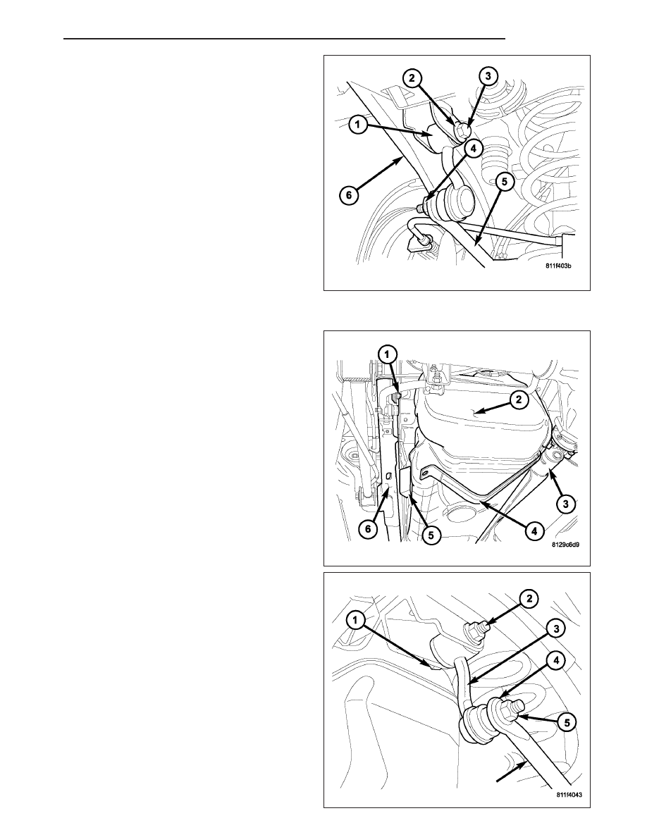
7. Remove the upper link nut (2) and bolt (3) at the

frame.

8. Remove the lower link nut (4) at the stabilizer bar

(5).

9. Remove stabilizer link (1).

INSTALLATION

1. Install the upper bolt (1) and nut (1) for the stabi-

lizer link to the frame and tighten to 102 N·m (75 ft.
lbs.).

2. Remove the block of wood (5) between the frame

(6) and fuel tank (2) If replacement of left stabi-
lizer link was performed
.

3. Install the rear fuel tank strap (4) If replacement of

left stabilizer link was performed.

4. Install the fuel tank skid plate (Refer to 13 -

FRAME & BUMPERS/FRAME/FUEL TANK SKID
PLATE - INSTALLATION). If replacement of left
stabilizer link was performed.

5. Install the stabilizer link (3) to the stabilizer bar (4).

6. Install the nut (5) and tighten to 102 N·m (75 ft.

lbs.).

7. Remove the jack and lower the vehicle.

HB

REAR

2 - 35

STABILIZER BAR

DESCRIPTION

The stabilizer bar extends across the underside of the vehicle and is bolted to the top of the axle. Links at the end
of the bar are bolted to the frame.

OPERATION

The stabilizer bar is used to minimize vehicle body sway. The spring steel bar helps to control the vehicle body in
relationship to the suspension.

REMOVAL

1. Raise and support vehicle.

2. Remove lower links mounting nuts (1).

3. Remove stabilizer bar retainer bolts (2) and retain-

ers (6) at the axle (4).

4. Remove the park brake cable bracket from the

retainers.

5. Remove stabilizer bar (3) and remove bushings (5).

INSTALLATION

1. Install stabilizer bar bushings (5).

2. Install the stabilizer bar (3) and center it with equal

spacing on both sides.

3. Install stabilizer bar retainers (6) and tighten bolts

(2) to 61 N·m (45 ft. lbs.).

4. Install the park brake cable bracket to the retainers.

5. Install the links (1) on the stabilizer bar (3). Install

mounting bolts and nuts.

6. Remove support and lower vehicle.

7. Tighten stabilizer link lower nuts (2) to 102 N·m (75

ft. lbs.).

2 - 36

REAR

HB

CONTROL ARM-LOWER

REMOVAL

1. Raise and support the rear axle.

2. Remove the lower control arm bolt (3) and flag nut

at the axle (2).

3. Remove the lower control arm bolt (1) and flag nut

(3) at the frame (2).

4. Remove the lower control arm (4) from the vehicle.

INSTALLATION

1. Install the lower control arm (4) to the vehicle.

2. Install the lower control arm bolt (1) and flag nut (3)

at the frame (2).

HB

REAR

2 - 37

3. Install the lower control arm bolt (3) and flag nut at

the axle (2).

4. Lower the vehicle to the ground and then tighten

the bolts to 251 N·m (185 ft.lbs.).

CONTROL ARM-UPPER

REMOVAL

1. Raise and support the rear axle.

2. Remove the upper control arm bolt (3) and flag nut

(4) at the axle (5).

3. Remove the upper control arm bolt and flag nut at

the frame side (1).

4. Remove the upper control arm (2) from the vehicle.

2 - 38

REAR

HB


Content   ..  15  16  17  18   ..