Dodge Dakota (R1). Manual - part 791


  Index      Dodge     Dodge Dakota (R1) - service repair manual 2000 year


Search            


Content   ..  789  790  791  792   ..


Dodge Dakota (R1). Manual - part 791


OPERATION

The high pressure relief valve vents the system when

a discharge pressure of 3445 to 4135 kPa (500 to 600
psi) or above is reached. The valve closes with a mini-
mum discharge pressure of 2756 kPa (400 psi) is
reached.

The high pressure relief valve vents only enough

refrigerant to reduce the system pressure, and then
re-seats itself. The majority of the refrigerant is con-
served in the system. If the valve vents refrigerant, it
does not mean the valve is faulty.

The high pressure relief valve is a factory-cali-

brated

unit.

The

valve

cannot

be

adjusted

or

repaired, and must not be removed or otherwise dis-
turbed. The valve is only serviced as a part of the
compressor assembly.

A/C COMPRESSOR CLUTCH

DESCRIPTION

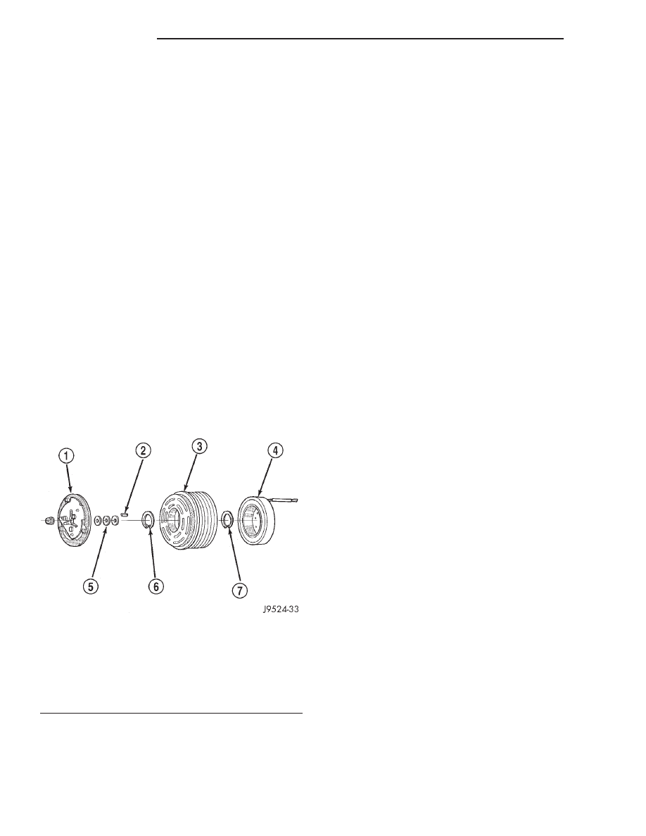
The compressor clutch assembly consists of a station-

ary electromagnetic coil, a hub bearing and pulley
assembly, and a clutch plate (Fig. 1). The electromag-
netic coil unit and the hub bearing and pulley assembly
are each retained on the nose of the compressor front
housing with snap rings. The clutch plate is mounted to
the compressor shaft and secured with a nut.

OPERATION

The compressor clutch assembly provides the

means to engage and disengage the compressor from
the engine serpentine accessory drive belt. When the

clutch coil is energized, it magnetically draws the
clutch into contact with the pulley and drives the
compressor shaft. When the coil is not energized, the
pulley freewheels on the clutch hub bearing, which is
part of the pulley. The compressor clutch and coil are
the only serviced parts on the compressor.

The compressor clutch engagement is controlled by

several components: the a/c heater mode control
switch, the a/c loss of charge switch, the a/c pressure
transducer, the compressor clutch relay, the evapora-
tor temperature sensor and the Powertrain Control
Module (PCM). The PCM may delay compressor
clutch engagement for up to thirty seconds (Refer to
8 - ELECTRICAL/ELECTRONIC CONTROL MOD-
ULES/POWERTRAIN

CONTROL

MODULE

-

DESCRIPTION).

DIAGNOSIS AND TESTING - A/C COMPRESSOR
CLUTCH COIL

For circuit descriptions and diagrams, (Refer to

Appropriate Wiring Information). The battery must
be fully-charged before performing the following tests
(Refer to 8 - ELECTRICAL/CHARGING - DIAGNO-
SIS AND TESTING).

(1) Connect an ammeter (0 to 10 ampere scale) in

series with the clutch coil terminal. Use a voltmeter
(0 to 20 volt scale) with clip-type leads for measuring
the voltage across the battery and the compressor
clutch coil.

(2) With the a/c select button depressed, and the

blower motor switch in the lowest speed position,
start the engine and run it at normal idle.

(3) The compressor clutch coil voltage should read

within 0.2 volts of the battery voltage. If there is
voltage at the clutch coil, but the reading is not
within 0.2 volts of the battery voltage, test the clutch
coil feed circuit for excessive voltage drop and repair
as required. If there is no voltage reading at the
clutch coil, use a DRB III

t scan tool and (Refer to

Appropriate Diagnostic Information) for testing of the
compressor clutch circuit. The following components
must be checked and repaired as required before you
can complete testing of the clutch coil:

• Fuses in the junction block and the Power Dis-

tribution Center (PDC)

• A/C Heater Control

• Compressor Clutch Relay

• A/C Pressure Transducer

• A/C Loss of Charge Pressure Switch

• Evaporator Temperature Sensor

• Powertrain Control Module (PCM)
(4) The compressor clutch coil is acceptable if the

current draw measured at the clutch coil is 2.0 to 3.9
amperes with the electrical system voltage at 11.5 to
12.5 volts. This should only be checked with the work
area temperature at 21° C (70° F). If system voltage

Fig. 1 COMPRESSOR CLUTCH - TYPICAL

1 - CLUTCH PLATE
2 - SHAFT KEY
3 - PULLEY
4 - COIL
5 - CLUTCH SHIMS
6 - SNAP RING
7 - SNAP RING

24 - 10

CONTROLS

AN

A/C COMPRESSOR HIGH PRESSURE RELIEF VALVE (Continued)

is more than 12.5 volts, add electrical loads by turn-
ing on electrical accessories until the system voltage
drops below 12.5 volts.

(a) If the clutch coil current reading is four

amperes or more, the coil is shorted and should be
replaced.

(b) If the clutch coil current reading is zero, the

coil is open and should be replaced.

STANDARD PROCEDURE - A/C COMPRESSOR
CLUTCH BREAK-IN

After a new compressor clutch has been installed,

cycle the compressor clutch approximately twenty
times (five seconds on, then five seconds off). During
this procedure, set the a/c heater control to the recir-
culation mode (Max-A/C), the blower motor switch to
the highest speed position, and the engine speed at
1500 to 2000 rpm. This procedure (burnishing) will
seat the opposing friction surfaces and provide a
higher compressor clutch torque capability.

REMOVAL

The refrigerant system can remain fully-charged

during compressor clutch, pulley, or coil replacement.
The compressor clutch can be serviced in the vehicle.

(1) Disconnect and isolate the battery negative cable.
(2) Remove the serpentine drive belt. Refer to

Cooling for the procedures.

(3) Unplug the compressor clutch coil wire harness

connector.

(4) Insert the two pins of the spanner wrench

(Special Tool 6462 in Kit 6460) into the holes of the
clutch plate. Hold the clutch plate stationary and
remove the hex nut (Fig. 2).

(5) Remove the clutch plate and the clutch shims.
(6) Remove the external front housing snap ring

with snap ring pliers (Fig. 3).

(7) Install the lip of the rotor puller (Special Tool

C-6141-1 in Kit 6460) into the snap ring groove
exposed in Step 6, and install the shaft protector
(Special Tool C-6141-2 in Kit 6460) (Fig. 4).

Fig. 2 CLUTCH NUT REMOVE

1 - FRONT PLATE SPANNER

Fig. 3 EXTERNAL SNAP RING REMOVE

1 - EXTERNAL SNAP RING

Fig. 4 SHAFT PROTECTOR AND PULLER

1 - PULLER SHAFT PROTECTOR
2 - JAWS

AN

CONTROLS

24 - 11

A/C COMPRESSOR CLUTCH (Continued)

(8) Install the puller through-bolts (Special Tool

C-6461) through the puller flange and into the jaws
of the rotor puller and tighten (Fig. 5). Turn the
puller center bolt clockwise until the rotor pulley is
free.

(9) Remove the screw and retainer from the clutch

coil lead wire harness on the compressor front hous-
ing (Fig. 6).

(10) Remove the snap ring from the compressor

hub and remove the clutch field coil (Fig. 7). Slide
the clutch field coil off of the compressor hub.

INSPECTION

Examine the friction surfaces of the clutch pulley

and the front plate for wear. The pulley and front
plate should be replaced if there is excessive wear or
scoring.

If the friction surfaces are oily, inspect the shaft

and nose area of the compressor for oil. Remove the
felt from the front cover. If the felt is saturated with
oil, the shaft seal is leaking and the compressor must
be replaced.

Check the clutch pulley bearing for roughness or

excessive leakage of grease. Replace the bearing, if
required.

INSTALLATION

(1) Install the clutch field coil and snap ring.

(2) Install the clutch coil lead wire harness retain-

ing clip on the compressor front housing and tighten
the retaining screw.

Fig. 5 INSTALL PULLER PLATE

1 - BOLT
2 - PULLER PLATE AND BOLT
3 - BOLT
4 - JAWS

Fig. 6 CLUTCH COIL LEAD WIRE HARNESS

1 - CLIP

Fig. 7 CLUTCH FIELD COIL SNAP RING REMOVE

1 - FIELD COIL
2 - SNAP RING

24 - 12

CONTROLS

AN

A/C COMPRESSOR CLUTCH (Continued)

(3) Align the rotor assembly squarely on the front

compressor housing hub.

(4) Thread the handle (Special Tool 6464 in Kit

6460) into the driver (Special Tool 6143 in Kit 6460)
(Fig. 8).

(5) Place the driver tool assembly into the bearing

cavity on the rotor. Make certain the outer edge of
the tool rests firmly on the rotor bearing inner race
(Fig. 9).

(6) Tap the end of the driver while guiding the

rotor to prevent binding. Tap until the rotor bottoms
against the compressor front housing hub. Listen for

a distinct change of sound during the tapping pro-
cess, to indicate the bottoming of the rotor.

(7) Install the external front rotor snap ring with

snap ring pliers. The bevel side of the snap ring must
be facing outward. Press the snap ring to make sure
it is properly seated in the groove.

CAUTION: If the snap ring is not fully seated in the
groove it will vibrate out, resulting in a clutch fail-
ure and severe damage to the front housing of the
compressor.

(8) Install the original clutch shims on the com-

pressor shaft.

(9) Install the clutch plate. Use the shaft protector

(Special Tool 6141-2 in Kit 6460) to install the clutch
plate on the compressor shaft (Fig. 10). Tap the
clutch plate over the compressor shaft until it has
bottomed against the clutch shims. Listen for a dis-
tinct change of sound during the tapping process, to
indicate the bottoming of the clutch plate.

(10) Replace the compressor shaft hex nut. Tighten

the nut to 14.4 N·m (10.5 ft. lbs.).

(11) Check the clutch air gap with a feeler gauge

(Fig. 11). If the air gap does not meet the specifica-
tion, add or subtract shims as required. The air gap
specification is 0.41 to 0.79 millimeter (0.016 to 0.031
inch). If the air gap is not consistent around the cir-
cumference of the clutch, lightly pry up at the mini-
mum variations. Lightly tap down at the points of
maximum variation.

Fig. 8 ROTOR INSTALLER SET

Fig. 9 ROTOR INSTALL

Fig. 10 CLUTCH PLATE INSTALL

AN

CONTROLS

24 - 13

A/C COMPRESSOR CLUTCH (Continued)


Content   ..  789  790  791  792   ..