Dodge Dakota (R1). Manual - part 789
air conditioning system on humid days. A perfor-
mance test is the best way to determine whether the
system is performing up to standard. This test also
provides valuable clues as to the possible cause of
trouble with the air conditioning system.
Before proceeding, (Refer to 24 - HEATING & AIR
CONDITIONING/PLUMBING
-
WARNING)
and
(Refer to 24 - HEATING & AIR CONDITIONING/
PLUMBING - CAUTION). The air temperature in
the test room and in the vehicle must be a minimum
of 21° C (70° F) for this test. Also the fin probe (locat-
ed in the evaporator of the HVAC unit) must be a
minimum of 65° for this test as well.
(1) Connect a tachometer and a manifold gauge
set.
(2) Set the a/c heater control to the recirculation
mode (Max-A/C) position, the temperature control
knob in the full cool position, and the blower motor
switch knob in the highest speed position.
(3) Start the engine and hold the idle at 1,000 rpm
with the compressor clutch engaged. If the compres-
sor does not engage, see the A/C Diagnosis chart in
the Diagnosis and Testing section of this group.
(4) The engine should be at operating temperature.
The doors and windows must be closed.
(5) Insert a thermometer in the driver side center
A/C (panel) outlet. Operate the a/c system until it
stabslizes.
(6) With the compressor clutch engaged, record the
discharge air temperature, the condenser out pres-
sure (high side), and the compressor inlet pressure
(low side). The compressor clutch may cycle, depend-
ing upon the ambient temperature and humidity. If
the clutch cycles, use the readings obtained before
the clutch disengaged.
(7) Compare the discharge air temperature read-
ing to the Performance Temperature and Pressure
chart. If the temperature reading is high, clamp off
both heater hoses (inlet and outlet), wait five min-
utes and record the temperature again. Compare the
second reading to the Performance Temperature and
Pressure chart. If the temperature reading is now
OK, see A/C Diagnosis chart for normal pressures. Or
see A/C Performance Test if air temperatures are too
high,
(8) Compare the discharge (high side) and suction
(low side) pressure readings to the Performance Tem-
perature and Pressure chart. If the pressures are
abnormal, see (Refer to 24 - HEATING & AIR CON-
DITIONING/PLUMBING - DIAGNOSIS AND TEST-
ING - REFRIGERANT SYSTEM LEAKS) and (Refer
to 24 - HEATING & AIR CONDITIONING/PLUMB-
ING - STANDARD PROCEDURE - REFRIGERANT
SYSTEM CHARGE).
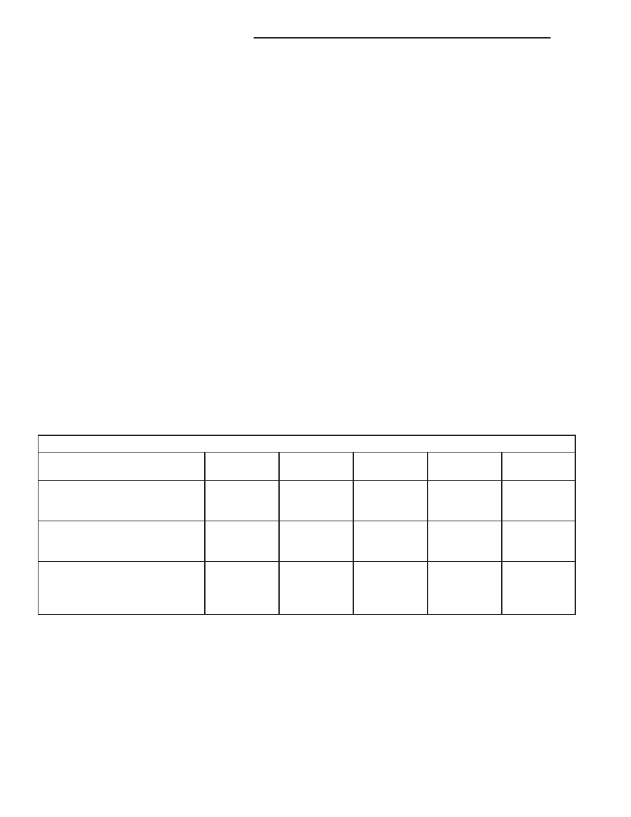
Performance Temperature and Pressure
Ambient Air Temperature
21°C
(70°F)
27°C
(80°F)
32°C
(90°F)
38°C
(100°F)
43°C
(110°F)
Maximum Allowable Air
Temperature at Center Panel
Outlet
7°C
(45°F)
7°C
(45°F)
13°C
(55°F)
13°C
(55°F)
18°C
(64°F)
Compressor Inlet Pressure at
Service Port (Low Side)
138 to 207
kPa
(20 to 30 psi)
172 to 241
kPa
(25 to 35 psi)
207 to 276
kPa
(30 to 40 psi)
241 to 310
kPa
(35 to 45 psi)
276 to 345
kPa
(40 to 50 psi)
Condensor Out Pressure at
Service Port (High Side)
1034 to 1724
kPa
(150 to 250
psi)
1379 to 2068
kPa
(200 to 300
psi)
1724 to 2413
kPa
(250 to 350
psi)
1999 to 2689
kPa
(290 to 390
psi)
2413 to 2965
kPa
(350 to 430
psi)
(9) Compare the compressor discharge and suction
(evaporator inlet) pressure readings to the Perfor-
mance Temperature and Pressure chart. If the com-
pressor discharge pressure or suction pressure is not
normal, see the Pressure Diagnosis chart.
24 - 2
HEATING & AIR CONDITIONING
AN
HEATING & AIR CONDITIONING (Continued)