Dodge Dakota (R1). Manual - part 774


  Index      Dodge     Dodge Dakota (R1) - service repair manual 2000 year


Search            


Content   ..  772  773  774  775   ..


Dodge Dakota (R1). Manual - part 774


(4) Install bolts attaching fender to hood hinge

support bracket.

(5) Install bolts attaching fender to lower radiator

closure panel.

(6) Install bolt attaching fender to lower rocker

panel.

(7) Position the wire harnesses on the inner fender

and wheelhouse and engage clips.

(8) Install powertrain control module.
(9) Install air cleaner element housing.
(10) Install right headlamp module.
(11) Install wheelhouse liner.
(12) Install wheel opening molding.
(13) Install right front wheel.
(14) Remove the support and lower the vehicle.
(15) Connect battery negative cable.

ROOF JOINT MOLDING

REMOVAL

(1) Warm the roof joint molding and roof panel to

approximately 38°C (100°F) using a suitable heat
lamp or heat gun.

(2) Pull molding from roof joint.

INSTALLATION

(1) Remove adhesive tape residue from roof joint.
(2) If molding is to be reused, remove tape residue

from back of molding. Clean molding with MOPAR,
Super Kleen solvent or equivalent. Wipe molding dry
with lint free cloth. Apply new body side molding
(two sided adhesive) tape to back of molding.

(3) Clean roof joint with MOPAR, Super Kleen sol-

vent or equivalent. Wipe dry with lint free cloth.

(4) Remove protective cover from tape on back of

molding and apply molding to roof joint.

(5) Heat roof and molding, see step one. Firmly

press molding into roof joint to assure adhesion.

SIDE VIEW MIRROR

REMOVAL

(1) Remove door trim panel.
(2) Remove mirror flag seal (Fig. 12).
(3) Disengage power mirror wire connector from

door harness, if equipped (Fig. 13).

(4) Remove nuts attaching side view mirror to door

frame.

(5) Separate harness grommet form door frame, if

equipped.

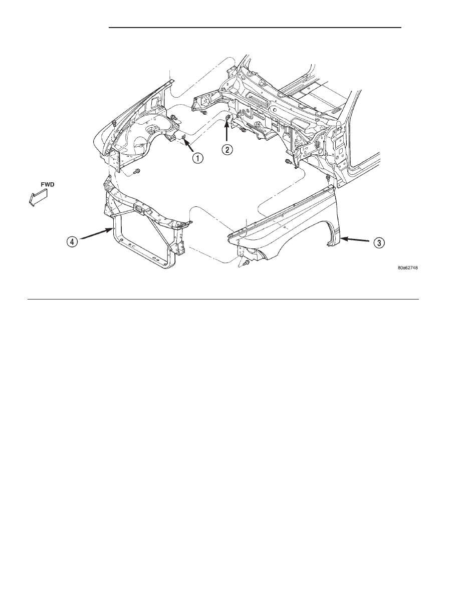
Fig. 11 Front Fender

1 - U-NUT
2 - U-NUT

3 - FRONT FENDER
4 - RADIATOR CLOSURE PANEL

23 - 84

EXTERIOR

AN

RIGHT FRONT FENDER (Continued)

(6) Separate side view mirror from vehicle.

INSTALLATION

(1) Position side view mirror on vehicle.
(2) Install harness grommet in door frame, if

equipped.

(3) Install nuts attaching side view mirror to door

frame. Tighten nuts to 7 N·m (65 in. lbs.) torque.

(4) Engage power mirror wire connector from door

harness, if equipped.

(5) Install mirror flag seal.
(6) Install door trim panel.

WHEEL OPENING MOLDING

REMOVAL

(1) Remove the screws attaching the wheel open-

ing molding to the fender (Fig. 1).

(2) Separate the molding from the wheel opening.

INSTALLATION

(1) Clean body surface with MOPAR Super Kleen

solvent or equivalent. Wipe surface dry with lint free
cloth.

(2) Position the molding in the wheel opening.
(3) Remove the backing and press to secure mold-

ing.

(4) Install the screws attaching the wheel opening

molding to the fender.

Fig. 12 Mirror Flag Door Seal

1 - STUFFERS
2 - MIRROR FLAG SEAL

Fig. 13 Side View Mirror Connectors

1 - ELECTRIC FOLD AWAY SIDEVIEW MIRROR
2 - DOOR
3 - ELECTRIC SIDEVIEW MIRROR

AN

EXTERIOR

23 - 85

SIDE VIEW MIRROR (Continued)

HOOD

TABLE OF CONTENTS

page

page

HOOD HINGE

REMOVAL . . . . . . . . . . . . . . . . . . . . . . . . . . . . . . 86
INSTALLATION. . . . . . . . . . . . . . . . . . . . . . . . . . . 86

HOOD

REMOVAL . . . . . . . . . . . . . . . . . . . . . . . . . . . . . . 86
INSTALLATION. . . . . . . . . . . . . . . . . . . . . . . . . . . 87
ADJUSTMENTS . . . . . . . . . . . . . . . . . . . . . . . . . . 87

HOOD SILENCER PAD

REMOVAL . . . . . . . . . . . . . . . . . . . . . . . . . . . . . . 87
INSTALLATION. . . . . . . . . . . . . . . . . . . . . . . . . . . 87

HOOD LATCH

REMOVAL . . . . . . . . . . . . . . . . . . . . . . . . . . . . . . 87

INSTALLATION. . . . . . . . . . . . . . . . . . . . . . . . . . . 88
ADJUSTMENTS . . . . . . . . . . . . . . . . . . . . . . . . . . 88

HOOD RELEASE CABLE

REMOVAL . . . . . . . . . . . . . . . . . . . . . . . . . . . . . . 88
INSTALLATION. . . . . . . . . . . . . . . . . . . . . . . . . . . 88

LATCH STRIKER

ADJUSTMENTS . . . . . . . . . . . . . . . . . . . . . . . . . . 89

HOOD SAFETY LATCH

REMOVAL . . . . . . . . . . . . . . . . . . . . . . . . . . . . . . 89
INSTALLATION. . . . . . . . . . . . . . . . . . . . . . . . . . . 89

HOOD HINGE

REMOVAL

(1) Open hood and support the side that requires

hinge replacement.

(2) Remove cowl grille.
(3) Mark all bolt and hinge attachment locations

with a grease pencil or other suitable device to pro-
vide reference marks for installation.

(4) Remove the nuts attaching the hinge to the

hood (Fig. 1).

(5) Remove the bolts attaching the hinge to the

inner fender (Fig. 1).

(6) Separate hinge from vehicle.

INSTALLATION

(1) If necessary, paint new hinge before installa-

tion.

(2) Position the hinge on the vehicle and align all

marks.

(3) Install the bolts attaching the hinge to the

inner fender. Tighten the bolts to 28.2 N·m (250 in.
lbs.) torque.

(4) Install the nuts attaching the hinge to the

hood. Tighten the nuts to 22.6 N·m (200 in. lbs )
torque.

(5) Install cowl grille.
(6) Remove support and verify hood operation. The

hood should be aligned to 5 mm (0.2 in.) gap to the
front fenders.

HOOD

REMOVAL

(1) Release primary hood latch.
(2) Release hood safety catch and open hood.
(3) Disconnect the under hood lamp wire connec-

tor.

(4) Mark all nut and hinge attachment locations

with a grease pencil or other suitable device to pro-
vide reference marks for installation.

(5) Remove the top nuts attaching hood to hinge

and loosen the bottom nuts until they can be
removed by hand (Fig. 2).

(6) With assistance of a helper, support the hood at

the opposite side of the vehicle.

(7) Remove the bottom nuts and separate the hood

from the vehicle.

Fig. 1 Hood Hinge

1 - HOOD
2 - HOOD HINGE

23 - 86

HOOD

AN

INSTALLATION

(1) With assistance of a helper, position the hood

on hinges.

(2) Align all marks and install the nuts. The hood

should be aligned to 5 mm (0.2 in.) gap to the front
fenders and flush across the top surfaces along fend-
ers.

(3) Connect the under hood lamp wire connector.
(4) Close hood and adjust as necessary.

ADJUSTMENTS

(1) Loosen the hinge arm-to-hood panel bolts at

each side of the vehicle.

(2) Loosen the hood latch screws.
(3) Close the hood. Adjust the fore/aft position.
(4) Raise the hood. Tighten the hinge arm-to-hood

panel bolts.

(5) Tighten the latch screws.
(6) Lower the hood. Inspect clearance between the

hood and the cowl cover.

HOOD SILENCER PAD

REMOVAL

(1) Raise the hood.
(2) Remove the retainers attaching the silencer

pad to the hood (Fig. 3).

(3) Remove the silencer pad from the hood.

INSTALLATION

(1) Position the silencer pad on the hood.
(2) Install the retainers attaching the silencer pad

to the hood.

(3) Close the hood.

HOOD LATCH

REMOVAL

(1) Release primary hood latch.
(2) Release hood safety catch and open hood.
(3) Using a grease pencil, mark latch position for

installation alignment.

(4) Remove bolts attaching hood latch to radiator

closure panel crossmember (Fig. 4).

(5) Separate hood latch from crossmember.
(6) Disconnect release cable from hood latch (Fig.

5).

Fig. 2 Hood

1 - HOOD
2 - HOOD HINGE

Fig. 3 Hood Silencer Pad

1 - HOOD
2 - RETAINER
3 - HOOD SILENCER PAD

Fig. 4 Hood Latch

1 - RADIATOR CLOSURE PANEL
2 - HOOD RELEASE CABLE
3 - HOOD LATCH
4 - LATCH BRACKET

AN

HOOD

23 - 87

HOOD (Continued)


Content   ..  772  773  774  775   ..