Dodge Dakota (R1). Manual - part 775


  Index      Dodge     Dodge Dakota (R1) - service repair manual 2000 year


Search            


Content   ..  773  774  775  776   ..


Dodge Dakota (R1). Manual - part 775


INSTALLATION

(1) Connect release cable to hood latch.
(2) Position hood latch on crossmember. Ensure

the bottom flange of hood latch (Fig. 5) is secured
around the latch bracket (Fig. 4).

(3) Install the bolts attaching hood latch to radia-

tor closure panel crossmember. Tighten the bolts to
10.7 N·m (80 in. lbs.) torque.

(4) Close hood.
(5) Adjust latch as necessary.

ADJUSTMENTS

(1) Open the hood.
(2) Loosen the hood latch screws.
(3) Move the latch to the correct location and

lightly tighten the screws.

(4) Close the hood slowly and observe the latching

operation.

(5) As necessary, adjust the latch position and

tighten the screws.

HOOD RELEASE CABLE

REMOVAL

(1) Release primary hood latch.
(2) Release hood safety catch and open hood.
(3) Remove hood latch.

(4) Disconnect release cable from hood latch (Fig.

5).

(5) Detach the release cable and the retainer clips

in the engine compartment.

(6) Separate the release cable grommet from the

dash panel hole.

(7) From the inside of the vehicle, remove the

screws attaching the hood release handle to the bot-
tom of the instrument panel (Fig. 6).

(8) Pull/route the hood release cable through the

dash panel hole and remove it via the inside of the
vehicle.

INSTALLATION

NOTE: If replacement hood latch is also being
installed, ensure that it is thoroughly lubricated.

(1) From inside the vehicle, pull/route the hood

release cable through the dash panel hole and into
the engine compartment.

(2) Install the hood release handle.
(3) Install the cable grommet in the dash panel

hole.

(4) Attach the retainer clips to the release cable

and install them into the holes in the engine com-
partment.

(5) Attach release cable to hood latch.
(6) Install hood latch.
(7) Test the hood latch release cable for proper

operation.

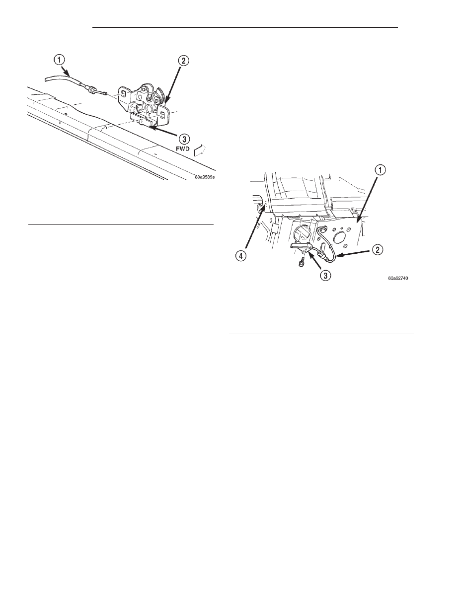
Fig. 5 Hood Release Cable

1 - HOOD RELEASE CABLE
2 - HOOD LATCH
3 - BOTTOM FLANGE

Fig. 6 Hood Release Cable

1 - DASH PANEL
2 - HOOD RELEASE CABLE
3 - HOOD RELEASE HANDLE
4 - INSTRUMENT PANEL

23 - 88

HOOD

AN

HOOD LATCH (Continued)

LATCH STRIKER

ADJUSTMENTS

(1) Open the hood.
(2) Loosen the latch striker screws.
(3) Slowly close the hood and observe the latching

operation.As necessary, adjust the striker position.
Tighten the screws.

HOOD SAFETY LATCH

REMOVAL

(1) Release primary hood latch.
(2) Release hood safety catch and open hood.
(3) Remove bolts attaching hood safety latch to

hood (Fig. 7).

(4) Separate safety latch from hood.

INSTALLATION

(1) Position safety latch on hood.
(2) Install bolts attaching safety latch to hood.

Tighten the bolts to 9.6 N·m (85 in. lbs.) torque.

(3) Close hood and verify operation. Adjust as nec-

essary.

Fig. 7 Hood Safety Latch

1 - HOOD
2 - SAFETY LATCH
3 - HINGE

AN

HOOD

23 - 89

INSTRUMENT PANEL SYSTEM

TABLE OF CONTENTS

page

page

INSTRUMENT PANEL SYSTEM

DESCRIPTION . . . . . . . . . . . . . . . . . . . . . . . . . . . 90
OPERATION. . . . . . . . . . . . . . . . . . . . . . . . . . . . . 91
REMOVAL . . . . . . . . . . . . . . . . . . . . . . . . . . . . . . 92
INSTALLATION. . . . . . . . . . . . . . . . . . . . . . . . . . . 93

ASH RECEIVER

REMOVAL . . . . . . . . . . . . . . . . . . . . . . . . . . . . . . 95
DISASSEMBLY. . . . . . . . . . . . . . . . . . . . . . . . . . . 95
ASSEMBLY . . . . . . . . . . . . . . . . . . . . . . . . . . . . . 96
INSTALLATION. . . . . . . . . . . . . . . . . . . . . . . . . . . 97

BASE TRIM

REMOVAL . . . . . . . . . . . . . . . . . . . . . . . . . . . . . . 97
INSTALLATION. . . . . . . . . . . . . . . . . . . . . . . . . . . 98

CLUSTER BEZEL

REMOVAL . . . . . . . . . . . . . . . . . . . . . . . . . . . . . . 98
INSTALLATION. . . . . . . . . . . . . . . . . . . . . . . . . . . 99

DEFROSTER GRILLE

REMOVAL . . . . . . . . . . . . . . . . . . . . . . . . . . . . . . 99
INSTALLATION . . . . . . . . . . . . . . . . . . . . . . . . . . 100

END CAP

REMOVAL . . . . . . . . . . . . . . . . . . . . . . . . . . . . . 100
INSTALLATION . . . . . . . . . . . . . . . . . . . . . . . . . . 100

GLOVE BOX

REMOVAL . . . . . . . . . . . . . . . . . . . . . . . . . . . . . 101

DISASSEMBLY . . . . . . . . . . . . . . . . . . . . . . . . . . 101
ASSEMBLY . . . . . . . . . . . . . . . . . . . . . . . . . . . . 102
INSTALLATION . . . . . . . . . . . . . . . . . . . . . . . . . . 102

GLOVE BOX LATCH STRIKER

REMOVAL . . . . . . . . . . . . . . . . . . . . . . . . . . . . . 103
INSTALLATION . . . . . . . . . . . . . . . . . . . . . . . . . . 104

INSIDE HOOD RELEASE BRACKET

REMOVAL . . . . . . . . . . . . . . . . . . . . . . . . . . . . . 104
INSTALLATION . . . . . . . . . . . . . . . . . . . . . . . . . . 105

LOWER BEZEL

REMOVAL . . . . . . . . . . . . . . . . . . . . . . . . . . . . . 105
INSTALLATION . . . . . . . . . . . . . . . . . . . . . . . . . . 106

STEERING COLUMN OPENING COVER

REMOVAL . . . . . . . . . . . . . . . . . . . . . . . . . . . . . 106
INSTALLATION . . . . . . . . . . . . . . . . . . . . . . . . . . 107

STORAGE BIN

REMOVAL . . . . . . . . . . . . . . . . . . . . . . . . . . . . . 107
INSTALLATION . . . . . . . . . . . . . . . . . . . . . . . . . . 108

TOP COVER

REMOVAL . . . . . . . . . . . . . . . . . . . . . . . . . . . . . 108
INSTALLATION . . . . . . . . . . . . . . . . . . . . . . . . . . 109

INSTRUMENT PANEL SYSTEM

DESCRIPTION

The instrument panel is located at the front of the

passenger compartment (Fig. 1). This instrument
panel is molded from a blend of various plastics that
are mechanically attached to the vehicle. Colors are
molded into the plastic components to minimize
appearance degradation from scratches or abrasions.
The panel components are internally ribbed and riv-
eted to steel reinforcements for additional structural
integrity and dimensional stability. The instrument
panel surface components are designed to deform
upon impact without breaking. This type of construc-
tion provides improved energy absorption which, in
conjunction with the dual airbags and seat belts,
helps to improve occupant protection.

The instrument panel for this vehicle includes the

following major features:

• Cluster Bezel - This molded plastic bezel is

secured with two screws and snap clips to the instru-
ment panel supporting structure. It trims out the
edges of the headlamp switch, instrument cluster,

radio, heater-air conditioner controls, the passenger
airbag on-off switch or rear window defogger switch
on vehicles so equipped, and the 4WD transfer case
switch on vehicles so equipped. On vehicles without
the passenger airbag on-off switch or rear window
defogger switch, a small storage cubby bin is pro-
vided in the cluster bezel. Likewise, on vehicles with-
out the optional four-wheel drive system, a small
storage cubby bin is provided in the cluster bezel.
This bezel also incorporates five completely adjust-
able panel outlets for the climate control system, and
fills the opening between the instrument cluster and
the top of the steering column where it passes
through the instrument panel.

• End Caps - A molded plastic end cap is secured

with snap clips to each outboard end of the instru-
ment panel. The end cap on the right end of the
instrument panel is primarily cosmetic. The end cap
on the left end of the instrument panel doubles as a
fuse access panel for the Junction Block (JB) and fea-
tures an integral pull cup on its outer surface to ease
removal, while a fuse layout map, a fuse puller and
spare fuses are conveniently concealed on its inner
surface.

23 - 90

INSTRUMENT PANEL SYSTEM

AN

• Glove Box - The modular glove box in the pas-

senger side of the instrument panel features a
recessed paddle-operated latch handle, a storage bin-
type glove box, and a fixed owner’s manual shelf at
the top of the glove box opening. A metal hinge on
the lower edge of the glove box door is riveted to the
module and secured with screws to the lower edge of
the instrument panel support structure. The glove
box door also serves as the passenger side knee
blocker. A honeycomb structure between the inner
and outer glove box door panels helps to absorb the
impact load and distribute it to the instrument panel
structure.

• Lower Bezel - The instrument panel lower

bezel is located on the lower edge of the instrument
panel, near the center. This bezel features an ash
receiver with a hinged door that is secured with a
push/push-type latch and an integral cigar lighter, an
accessory power outlet, and a center stack light that
illuminates the storage tray at the front of the center
floor console on the floor panel transmission tunnel
below.

• Steering Column Opening Cover - The steer-

ing column opening cover serves as the driver side
knee blocker. This molded plastic cover has an inte-
gral ribbed plastic liner concealed behind it, for
increased strength and integrity. The steering column
opening cover transfers impact loads to the instru-
ment panel structural support. A paddle-type parking

brake release handle is also incorporated in the lower
left corner of the steering column opening cover.

• Top Cover - The instrument panel top cover is

the molded, grained, and color impregnated plastic
panel that forms the top of the instrument panel.
This panel features an integral hood formation over
the instrument cluster on the left side and two inte-
gral storage tray formations over the right side. A
removable side window demister outlet is incorpo-
rated near each outboard end of the top cover.

Hard wired circuitry connects the electrical compo-

nents on the instrument panel to each other through
the electrical system of the vehicle. These hard wired
circuits are integral to several wire harnesses, which
are routed throughout the vehicle and retained by
many different methods. These circuits may be con-
nected to each other, to the vehicle electrical system
and to the instrument panel components through the
use of a combination of soldered splices, splice block
connectors and many different types of wire harness
terminal connectors and insulators. Refer to the
appropriate wiring information. The wiring informa-
tion includes complete circuit diagrams, proper wire
and connector repair procedures, further details on
wire harness routing and retention, as well as pin-
out and location views for the various wire harness
connectors, splices, and grounds.

OPERATION

The instrument panel serves as the command cen-

ter of the vehicle, which necessarily makes it a very
complex unit. The instrument panel is designed to
house the controls and monitors for standard and
optional powertrains, climate control systems, audio
systems, safety systems, and many other comfort or
convenience items. When the components of the
instrument panel structural support are properly
assembled and secured in the vehicle they provide
superior instrument panel stiffness and integrity to
help reduce buzzes, squeaks, and rattles. This type of
construction also provides improved energy absorp-
tion which, in conjunction with the dual airbags and
seat belts, helps to improve occupant protection.

The instrument panel is also designed so that all of

the various controls can be safely reached and the
monitors can be easily viewed by the vehicle operator
when driving, while still allowing relative ease of
access to each of these items for service. Modular
instrument panel construction allows all of the
gauges and controls to be serviced from the front of
the panel. In addition, most of the instrument panel
electrical components can be accessed without com-
plete instrument panel removal. However, if neces-
sary, the instrument panel can be removed from the
vehicle as an assembly.

Fig. 1 Instrument Panel

1 - DEFROSTER GRILLE
2 - CLUSTER BEZEL
3 - TOP COVER
4 - LOWER BEZEL
5 - END CAP
6 - INSTRUMENT PANEL

AN

INSTRUMENT PANEL SYSTEM

23 - 91

INSTRUMENT PANEL SYSTEM (Continued)


Content   ..  773  774  775  776   ..