Dodge Dakota (R1). Manual - part 773
 

  Index      Dodge     Dodge Dakota (R1) - service repair manual 2000 year


Search            


Content   ..  771  772  773  774   ..


Dodge Dakota (R1). Manual - part 773


EXTERIOR NAME PLATES

REMOVAL

NOTE: Exterior nameplates are attached to body
panels with adhesive tape.

(1) Apply a length of masking tape on the body,

parallel to the top edge of the nameplate to use as a
guide, if necessary.

(2) If temperature is below 21°C (70°F) warm

emblem with a heat lamp or gun. Do not exceed 52°C
(120°F) when heating emblem.

(3) Insert a plastic trim stick or a hard wood

wedge behind the emblem to separate the adhesive
backing from the body.

(4) Clean adhesive residue from body with MOPAR

Super Clean solvent or equivalent.

INSTALLATION

(1) Remove carrier from back of emblem.
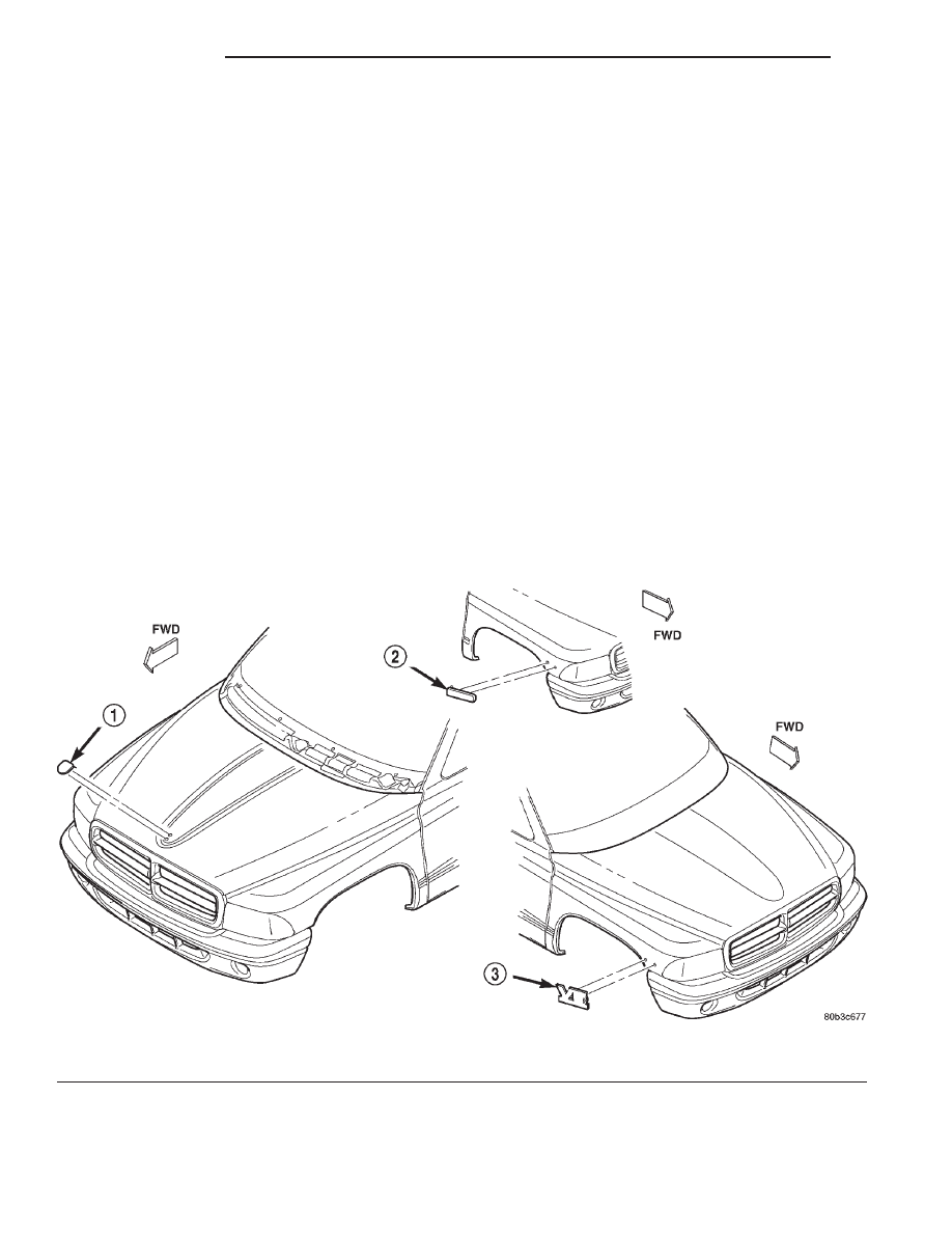
(2) Position emblem properly on body (Fig. 4).
(3) Press emblem firmly to body with palm of

hand.

(4) If temperature is below 21°C (70°F) warm

emblem with a heat lamp or gun to assure adhesion.
Do not exceed 52°C (120°F) when heating emblem.

FRONT END SPLASH SHIELDS

REMOVAL

(1) Raise and support the front wheel.
(2) Remove the front wheel.
(3) Remove wheel opening molding.
(4) Remove plastic rivets attaching wheelhouse

liner to wheelhouse (Fig. 5).

(5) Separate liner from vehicle.

INSTALLATION

(1) Position liner in wheelhouse.
(2) Install plastic rivets attaching wheelhouse liner

to wheelhouse.

(3) Install wheel opening molding.
(4) Install the front wheel.
(5) Remove the support and lower the vehicle.

Fig. 4 Exterior Nameplates

1 - HOOD NAME PLATE
2 - MAGNUM POWER NAME PLATE

3 - ENGINE NAME PLATE

23 - 80

EXTERIOR

AN

FUEL FILL DOOR

REMOVAL

(1) Open the fuel filler door.
(2) Remove the screws attaching the door to the

cargo box outer panel (Fig. 6).

(3) Remove the door from the panel.

INSTALLATION

(1) Position the fuel filler door on the cargo box

outer panel with the screw holes aligned.

(2) Install the screws attaching the fuel filler door

to the cargo box outer panel.

GRILLE

REMOVAL

(1) Release primary hood latch.
(2) Release hood safety catch and open hood.
(3) Remove screws attaching bottom of grille to

grille mounting bracket.

(4) Remove nuts attaching grille to hood (Fig. 7).
(5) Separate grille from vehicle.

Fig. 5 Front Wheelhouse Liner

1 - FENDER SPLASH SHIELD
2 - INNER FENDER
3 - INNER FENDER
4 - WHEELHOUSE LINER
5 - FENDER SPLASH SHIELD
6 - PLASTIC RIVET

7 - PLASTIC RIVET
8 - WHEELHOUSE LINER
9 - INNER FENDER
10 - WHEELHOUSE LINER
11 - PLASTIC RIVET

Fig. 6 Fuel Filler Door

1 - FUEL DOOR
2 - BUMPER

AN

EXTERIOR

23 - 81

FRONT END SPLASH SHIELDS (Continued)

INSTALLATION

(1) Position grille on hood.
(2) Install nuts attaching grille to hood.
(3) Install screws attaching bottom of grille to

grille mounting bracket.

(4) Close hood.

LEFT FRONT FENDER

REMOVAL

(1) Remove battery.
(2) Raise and support the vehicle.
(3) Remove left front wheel.
(4) Remove wheel opening molding.
(5) Remove wheelhouse liner.
(6) Remove left headlamp module.
(7) Remove PDC (power distribution center).
(8) Remove

battery

tray

and

battery

support

bracket (Fig. 8).

(9) Remove

HCU

(hydraulic

control

unit)

if

equipped. (Refer to 5 - BRAKES/HYDRAULIC/ME-
CHANICAL/HCU (HYDRAULIC CONTROL UNIT) -
REMOVAL)

(10) Disengage clips attaching hood release cable

to inner fender.

(11) Disengage clips attaching wire harness to

inner fender and wheelhouse.

(12) Remove bolt attaching fender to lower rocker

panel.

(13) Remove bolts attaching fender to lower radia-

tor closure panel (Fig. 8).

(14) Remove bolts attaching fender to hood hinge

support bracket.

(15) Remove bolts attaching fender to upper cowl

(Fig. 9).

(16) Remove bolts attaching fender to upper radia-

tor closure panel.

(17) Separate fender and wheelhouse from vehicle.

INSTALLATION

(1) Position fender and wheelhouse from vehicle.
(2) Install bolts attaching fender to upper radiator

closure panel.

(3) Install bolts attaching fender to upper cowl.
(4) Install bolts attaching fender to hood hinge

support bracket.

(5) Install bolts attaching fender to lower radiator

closure panel.

(6) Install bolt attaching fender to lower rocker

panel.

(7) Position the hood release cable to inner fender

and engage clips.

(8) Position the wire harnesses on the inner fender

and wheelhouse and engage clips.

Fig. 7 Grille

1 - GRILLE
2 - GRILLE MOUNTING BRACKET

Fig. 8 Battery Tray and Support Bracket

1 - FRONT FENDER
2 - BATTERY TRAY SUPPORT BRACKET
3 - BATTERY TRAY

23 - 82

EXTERIOR

AN

GRILLE (Continued)

(9) Install HCU if equipped. (Refer to 5 - BRAKES/

HYDRAULIC/MECHANICAL/HCU

(HYDRAULIC

CONTROL UNIT) - INSTALLATION)

(10) Install battery support bracket and battery

tray.

(11) Install PDC (power distribution center).
(12) Install left headlamp module.
(13) Install battery.
(14) Install wheelhouse liner.
(15) Install wheel opening molding.
(16) Install left front wheel.
(17) Remove the support and lower the vehicle.

REAR WHEELHOUSE SPLASH
SHIELD

REMOVAL

(1) Remove bottom screw attaching wheel opening

molding to cargo box.

(2) Remove screws attaching splash shield to inner

wheel house (Fig. 10).

(3) Separate splash shield from vehicle.

INSTALLATION

(1) Position splash shield in wheel house.
(2) Install screws attaching splash shield to inner

wheel house.

(3) Install bottom screw attaching wheel opening

molding to cargo box.

RIGHT FRONT FENDER

REMOVAL

(1) Disconnect battery negative cable.
(2) Raise and support the vehicle.
(3) Remove right front wheel.
(4) Remove wheel opening molding.
(5) Remove wheelhouse liner.
(6) Remove right headlamp module.
(7) Remove air cleaner element housing.
(8) Remove powertrain control module.
(9) Disengage clips attaching wire harnesses to

inner fender and wheelhouse.

(10) Remove bolt attaching fender to lower rocker

panel.

(11) Remove bolts attaching fender to lower radia-

tor closure panel (Fig. 11).

(12) Remove bolts attaching fender to hood hinge

support bracket.

(13) Remove bolts attaching fender to upper cowl.
(14) Remove bolts attaching fender to upper radia-

tor closure panel.

(15) Separate fender and wheelhouse from vehicle.

INSTALLATION

(1) Position fender and wheelhouse from vehicle.
(2) Install bolts attaching fender to upper radiator

closure panel.

(3) Install bolts attaching fender to upper cowl.

Fig. 9 Front Fender

1 - FRONT FENDER
2 - BRACKET
3 - U-NUT
4 - DASH PANEL
5 - U-NUT

Fig. 10 Rear Splash Shield

1 - U-NUT
2 - REAR SPLASH SHIELD
3 - FRONT SPLASH SHIELD
4 - U-NUT
5 - CARGO BOX
6 - U-NUT
7 - U-NUT

AN

EXTERIOR

23 - 83

LEFT FRONT FENDER (Continued)


Content   ..  771  772  773  774   ..