Dodge Dakota (R1). Manual - part 744


  Index      Dodge     Dodge Dakota (R1) - service repair manual 2000 year


Search            


Content   ..  742  743  744  745   ..


Dodge Dakota (R1). Manual - part 744


COUNTERSHAFT

Inspect the countershaft gear teeth. Replace the

countershaft if any teeth are worn or damaged.

Inspect the bearing surfaces and replace shaft if any
surface shows damage or wear.

Check condition of the countershaft front bearing.

Replace the bearing if worn, noisy, or damaged.

GEAR AND SYNCHRONIZER

Install the needle bearings in the first, second,

third and counter fifth gears. Install the gears on the
output shaft. Then check oil clearance between the
gears and shaft with a dial indicator (Fig. 57). Oil
clearance for all three gears is 0.16 mm (0.0063 in.)
maximum.

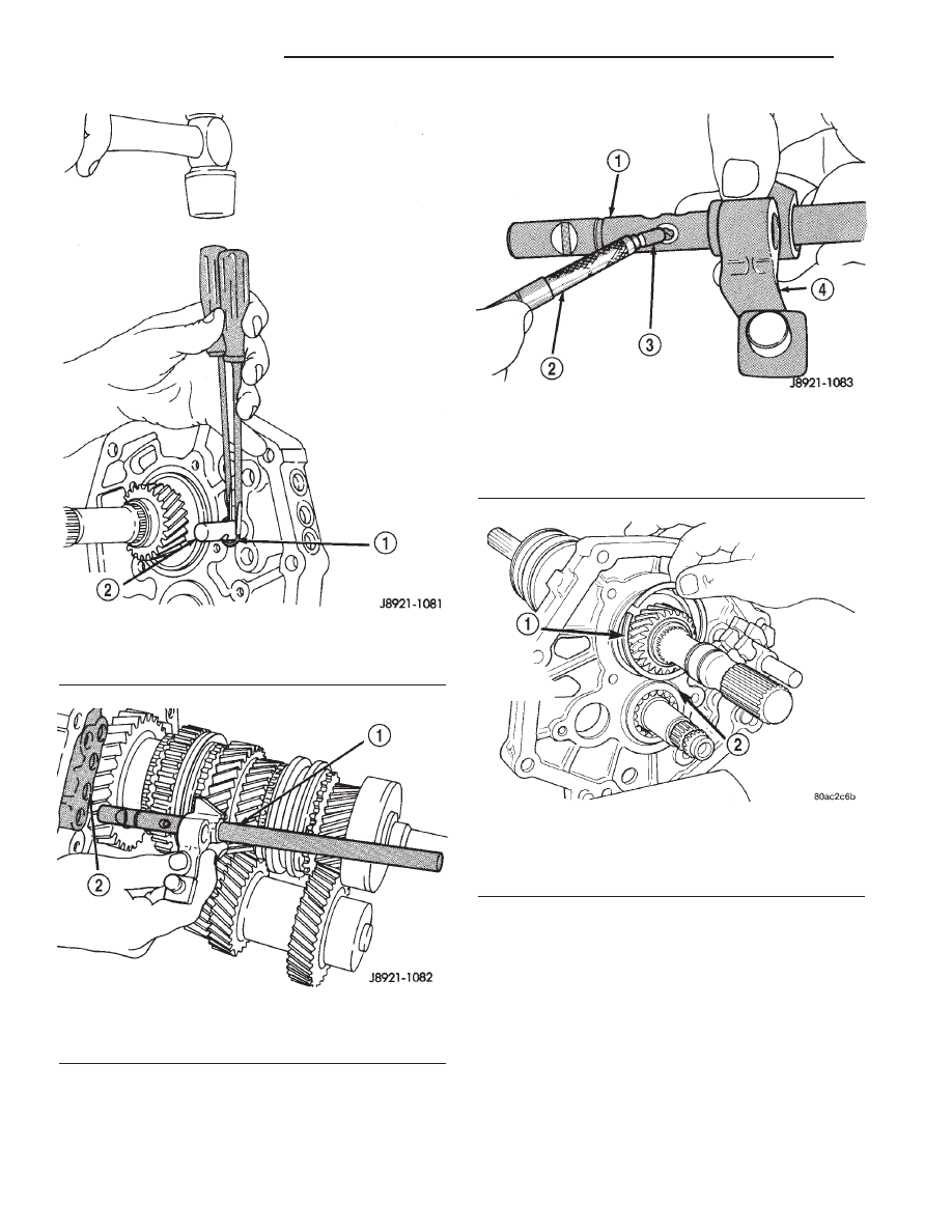
Fig. 51 REVERSE SHIFT RAIL C-RING

1 - C-RING
2 - REVERSE SHIFT RAIL

Fig. 52 REVERSE SHIFT RAIL

1- REVERSE SHIFT RAIL AND FORK
2 - REVERSE SHIFT RAIL BORE

Fig. 53 REVERSE SHIFT RAIL INTERLOCK PIN

1 - REVERSE SHIFT RAIL
2 - MAGNET
3 - INTERLOCK PIN
4 - REVERSE SHIFT FORK

Fig. 54 OUTPUT SHAFT REAR BEARING SNAP-

RING

1 - OUTPUT SHAFT REAR BEARING SNAP-RING
2 - COUNTERSHAFT REAR BEARING SNAP-RING

21a - 18

MANUAL - AX15

R1

MANUAL - AX15 (Continued)

Check synchronizer ring wear (Fig. 58). Insert each

ring in matching gear. Measure clearance between
each ring and gear with feeler gauge. Clearance
should be 0.06 - 1.6 mm (0.024 - 0.063 in.).

Check shift fork-to-synchronizer hub clearance

with a feeler gauge (Fig. 59). Replace the fork if
clearance exceeds 1.0 mm (0.039 in.).

Check the condition of the reverse idler gear bush-

ing (Fig. 60). Replace the gear if the bushing is dam-
aged or worn.

ASSEMBLY

SHIFT MECHANISM AND GEARTRAIN

(1) Lubricate countershaft journal and rear bear-

ing with petroleum jelly or gear lubricant.

(2) Position the mainshaft into the intermediate

plate.

(3) Tap mainshaft assembly rear bearing into the

intermediate plate with a rubber mallet.

(4) Install countershaft thru the countershaft rear

bearing journal of the intermediate plate.

(5) Align and mesh the mainshaft and counter-

shaft gears as much as possible.

Fig. 55 MAINSHAFT

1 - INPUT AND OUTPUT SHAFT GEAR ASSEMBLIES

Fig. 56 Check Output Shaft Tolerances

1 - CLUSTER GEAR JOURNAL

Fig. 57 Check Gear–To–Shaft Oil Clearance

1 - GEAR BEING CHECKED
2 - OUTPUT SHAFT

Fig. 58 Check Synchronizer Ring Wear

1 - FEELER GAUGE
2 - SYNCHRONIZER RING

R1

MANUAL - AX15

21a - 19

MANUAL - AX15 (Continued)

(6) Install countershaft bearing over the counter-

shaft bearing boss and into the intermediate plate.
Be sure to leave the snap-ring groove in the bearing
facing the rear of the unit. It may be necessary to tap
on the bearing with a plastic mallet to fully seat the
bearing into intermediate plate.

(7) Verify mainshaft and countershaft gears are

correctly meshed and rotate properly.

(8) Install snap-ring to hold output shaft rear

bearing into the intermediate plate (Fig. 61).

(9) Install countershaft rear bearing snap-ring.

NOTE: Coat all shift components with petroleum
jelly during assembly. Petroleum jelly will hold com-
ponents in position during installation.

(10) Install interlock pin in reverse shift rail (Fig.

62).

(11) Install reverse shift rail in the intermediate

plate (Fig. 63).

Fig. 59 Check Fork–To–Hub Clearance

1 - SHIFT FORK
2 - FEELER GAUGE
3 - SYNCHRONIZER SLEEVE

Fig. 60 Reverse Idler Gear Bushing

1 - CHECK BUSHING FOR WEAR OR DAMAGE
2 - REVERSE IDLER GEAR

Fig. 61 OUTPUT SHAFT REAR BEARING SNAP-

RING

1 - OUTPUT SHAFT REAR BEARING SNAP-RING
2 - COUNTERSHAFT REAR BEARING SNAP-RING

Fig. 62 REVERSE SHIFT RAIL INTERLOCK PIN

1 - REVERSE SHIFT RAIL
2 - MAGNET
3 - INTERLOCK PIN
4 - REVERSE SHIFT FORK

21a - 20

MANUAL - AX15

R1

MANUAL - AX15 (Continued)

(12) Install c-ring to hold the reverse shift rail into

the intermediate plate.

(13) Install 1-2 and 3-4 shift forks into the syn-

chronizer sleeves (Fig. 64).

(14) Install 1-2 shift rail interlock plug in the

intermediate plate (Fig. 65).

(15) Install interlock pin in 1-2 shift rail (Fig. 66).

Fig. 63 REVERSE SHIFT RAIL

1 - REVERSE SHIFT RAIL AND FORK
2 - REVERSE SHIFT RAIL BORE

Fig. 64 SHIFT FORKS

1 - 3-4 SHIFT FORK
2 - 1-2 SHIFT FORK

Fig. 65 1-2 SHIFT RAIL INTERLOCK PLUG

1 - 1-2 SHIFT RAIL INTERLOCK PLUG
2 - INTERMEDIATE PLATE
3 - MAGNET

Fig. 66 1-2 SHIFT RAIL INTERLOCK PIN

1 - 1-2 SHIFT RAIL INTERLOCK PIN
2 - 1-2 SHIFT RAIL
3 - MAGNET

R1

MANUAL - AX15

21a - 21

MANUAL - AX15 (Continued)


Content   ..  742  743  744  745   ..