Dodge Dakota (R1). Manual - part 720
STATOR
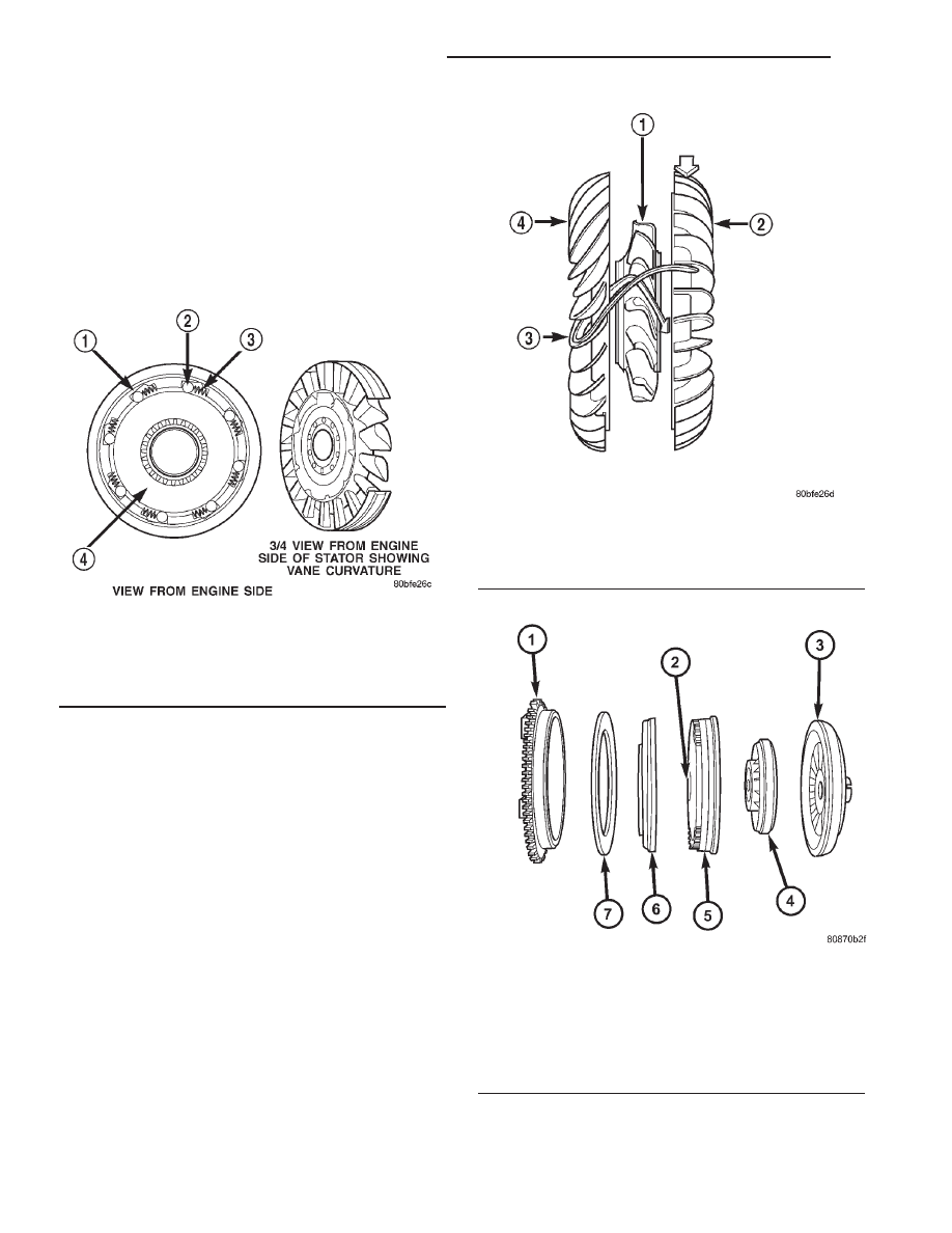
The stator assembly (Fig. 109) is mounted on a sta-
tionary shaft which is an integral part of the oil
pump. The stator is located between the impeller and
turbine within the torque converter case (Fig. 110).
The stator contains an over-running clutch, which
allows the stator to rotate only in a clockwise direc-
tion. When the stator is locked against the over-run-
ning clutch, the torque multiplication feature of the
torque converter is operational.
TORQUE CONVERTER CLUTCH (TCC)
The TCC (Fig. 111) was installed to improve the
efficiency of the torque converter that is lost to the
slippage of the fluid coupling. Although the fluid cou-
pling provides smooth, shock-free power transfer, it is
natural for all fluid couplings to slip. If the impeller
and turbine were mechanically locked together, a
zero slippage condition could be obtained. A hydraulic
piston with friction material was added to the tur-
bine assembly to provide this mechanical lock-up.
In order to reduce heat build-up in the transmis-
sion and buffer the powertrain against torsional
vibrations, the TCM can duty cycle the L/R-CC Sole-
noid to achieve a smooth application of the torque
converter clutch. This function, referred to as Elec-
tronically Modulated Converter Clutch (EMCC) can
occur at various times depending on the following
variables:
• Shift lever position
• Current gear range
• Transmission fluid temperature
• Engine coolant temperature
• Input speed
• Throttle angle
• Engine speed
Fig. 109 Stator Components
1 - CAM (OUTER RACE)
2 - ROLLER
3 - SPRING
4 - INNER RACE
Fig. 110 Stator Location
1 - STATOR
2 - IMPELLER
3 - FLUID FLOW
4 - TURBINE
Fig. 111 Torque Converter Clutch (TCC)
1 - IMPELLER FRONT COVER
2 - THRUST WASHER ASSEMBLY
3 - IMPELLER
4 - STATOR
5 - TURBINE
6 - PISTON
7 - FRICTION DISC
21 - 524
AUTOMATIC TRANSMISSION - 45RFE
AN
TORQUE CONVERTER (Continued)