Dodge Dakota (R1). Manual - part 718


  Index      Dodge     Dodge Dakota (R1) - service repair manual 2000 year


Search            


Content   ..  716  717  718  719   ..


Dodge Dakota (R1). Manual - part 718


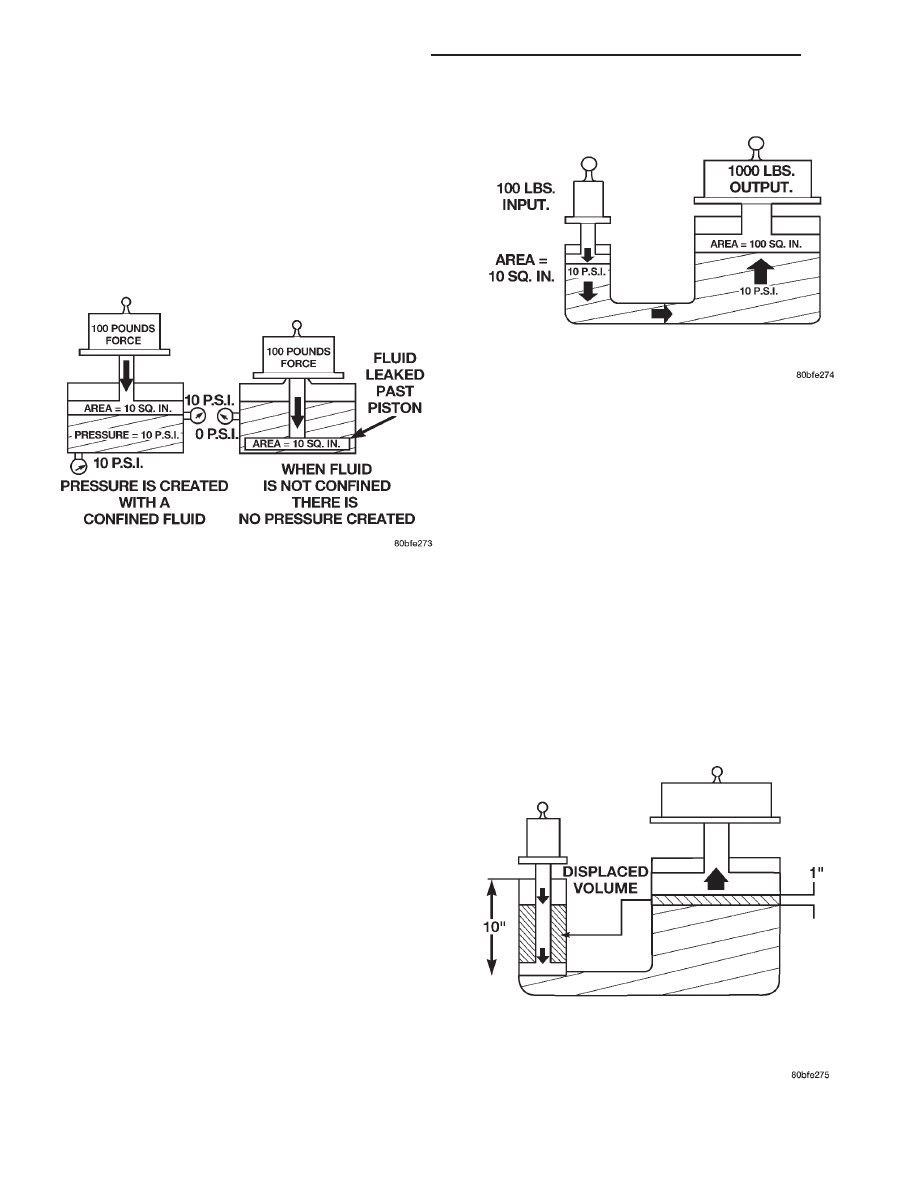
The pressure created in the fluid is equal to the force
applied, divided by the piston area. If the force is 100
lbs., and the piston area is 10 sq. in., then the pres-
sure created equals 10 PSI. Another interpretation of
Pascal’s Law is that regardless of container shape or
size, the pressure will be maintained throughout, as
long as the fluid is confined. In other words, the
pressure in the fluid is the same everywhere within
the container.

FORCE MULTIPLICATION

Using the 10 PSI example used in the illustration

(Fig. 101), a force of 1000 lbs. can be moved with a
force of only 100 lbs. The secret of force multiplica-
tion in hydraulic systems is the total fluid contact
area employed. The illustration, (Fig. 101), shows an
area that is ten times larger than the original area.
The pressure created with the smaller 100 lb. input
is 10 PSI. The concept “pressure is the same every-
where” means that the pressure underneath the
larger piston is also 10 PSI. Pressure is equal to the
force applied divided by the contact area. Therefore,
by means of simple algebra, the output force may be
found. This concept is extremely important, as it is
also used in the design and operation of all shift
valves and limiting valves in the valve body, as well
as the pistons, of the transmission, which activate
the clutches and bands. It is nothing more than
using a difference of area to create a difference in
pressure to move an object.

PISTON TRAVEL

The relationship between hydraulic lever and a

mechanical lever is the same. With a mechanical
lever it’s a weight-to-distance output rather than a
pressure-to-area output. Using the same forces and
areas as in the previous example, the smaller piston
(Fig. 102) has to move ten times the distance
required to move the larger piston one inch. There-
fore, for every inch the larger piston moves, the
smaller piston moves ten inches. This principle is
true in other instances also. A common garage floor
jack is a good example. To raise a car weighing 2000
lbs., an effort of only 100 lbs. may be required. For
every inch the car moves upward, the input piston at
the jack handle must move 20 inches downward.

Fig. 100 Pressure on a Confined Fluid

Fig. 101 Force Multiplication

Fig. 102 Piston Travel

21 - 516

AUTOMATIC TRANSMISSION - 45RFE

AN

PISTONS (Continued)

PLANETARY GEARTRAIN

DESCRIPTION

The planetary geartrain is located behind the 4C

retainer/bulkhead, toward the rear of the transmis-
sion. The planetary geartrain consists of three pri-
mary assemblies:

• Reaction (Fig. 103).

• Reverse (Fig. 104).

• Input (Fig. 104).

OPERATION

REACTION PLANETARY GEARTRAIN

The reaction planetary carrier and reverse sun

gear of the reaction planetary geartrain are a single
component which is held by the 2C clutch when
required. The reaction annulus gear is a stand alone

component that can be driven by the reverse clutch
or held by the 4C clutch. The reaction sun gear is
driven by the overdrive clutch.

REVERSE PLANETARY GEARTRAIN

The reverse planetary geartrain is the middle of

the three planetary sets. The reverse planetary car-
rier can be driven by the overdrive clutch as
required. The reverse planetary carrier is also
splined to the input annulus gear, which can be held
by the low/reverse clutch. The reverse planetary
annulus, input planetary carrier, and output shaft
are all one piece.

INPUT PLANETARY GEARTRAIN

The

input

sun

gear

of

the

input

planetary

geartrain is driven by the underdrive clutch.

Fig. 103 Reaction Planetary Geartrain

1 - BEARING NUMBER 8

5 - BEARING NUMBER 7

2 - BEARING NUMBER 9

6 - THRUST PLATE (SELECT)

3 - REACTION PLANETARY CARRIER

7 - BEARING NUMBER 6

4 - REACTION SUN GEAR

8 - REACTION ANNULUS

AN

AUTOMATIC TRANSMISSION - 45RFE

21 - 517

DISASSEMBLY

(1) Remove the snap-ring holding the input annu-

lus into the input carrier (Fig. 105).

(2) Remove the input annulus from the input car-

rier (Fig. 105).

(3) Remove the number 9 bearing from the reverse

planetary carrier. Note that this planetary carrier
has four pinion gears.

(4) Remove the reverse planetary gear carrier (Fig.

105).

(5) Remove the number 10 bearing from the input

sun gear (Fig. 105).

(6) Remove the input sun gear from the input car-

rier (Fig. 105).

(7) Remove the number 11 bearing from the input

carrier (Fig. 105).

CLEANING

Clean the planetary components in solvent and dry

them with compressed air.

INSPECTION

Check

sun

gear

and

driving

shell

condition.

Replace the gear if damaged or if the bushings are
scored or worn. The bushings are not serviceable.
Replace the driving shell if worn, cracked or dam-
aged.

Replace planetary gear sets if gears, pinion pins, or

carrier are damaged in any way. Replace the annulus
gears and supports if either component is worn or
damaged.

Replace the output shaft if the machined surfaces

are scored, pitted, or damaged in any way. Also
replace the shaft if the splines are damaged, or
exhibits cracks at any location.

ASSEMBLY

(1) Clean and inspect all components. Replace any

components which show evidence of excessive wear
or scoring.

(2) Install the number 11 bearing into the input

planetary carrier with the flat side up and facing for-
ward (Fig. 105).

Fig. 104 Reverse/Input Planetary Geartrain

1 - SNAP-RING

5 - INPUT PLANETARY CARRIER

2 - BEARING NUMBER 10

6 - INPUT SUN GEAR

3 - BEARING NUMBER 11

7 - REVERSE PLANETARY CARRIER

4 - INPUT ANNULUS

21 - 518

AUTOMATIC TRANSMISSION - 45RFE

AN

PLANETARY GEARTRAIN (Continued)

(3) Install the input sun gear into the input carrier

(Fig. 105).

(4) Install the number 10 bearing onto the rear of

the reverse planetary carrier with the flat side
toward the carrier (Fig. 105).

(5) Install the number 9 bearing onto the front of

the reverse planetary carrier with the rounded side
toward the carrier and the flat side facing upward
(Fig. 105).

(6) Install the reverse planetary gear carrier into

the input carrier (Fig. 105).

(7) Install the input annulus gear into the input

carrier (Fig. 105).

(8) Install the snap-ring to hold the input annulus

gear into the input carrier (Fig. 105).

SHIFT MECHANISM

DESCRIPTION

The gear shift mechanism provides six shift posi-

tions which are:

• Park (P)

• Reverse (R)

• Neutral (N)

• Drive (D)

• Manual second (2)

• Manual low (1)

OPERATION

MANUAL LOW (1) range provides first gear only.

Overrun braking is also provided in this range.
MANUAL SECOND (2) range provides first and sec-
ond gear only.

DRIVE range provides FIRST, SECOND THIRD

and OVERDRIVE FOURTH gear ranges. The shift
into OVERDRIVE FOURTH gear range occurs only
after the transmission has completed the shift into D
THIRD gear range. No further movement of the shift
mechanism is required to complete the 3-4 shift.

The FOURTH gear upshift occurs automatically

when the overdrive selector switch is in the ON posi-
tion. No upshift to FOURTH gear will occur if any of
the following are true:

Fig. 105 Reverse/Input Planetary Carrier Assembly

1 - SNAP-RING

5 - INPUT PLANETARY CARRIER

2 - BEARING NUMBER 10

6 - INPUT SUN GEAR

3 - BEARING NUMBER 11

7 - REVERSE PLANETARY CARRIER

4 - INPUT ANNULUS

AN

AUTOMATIC TRANSMISSION - 45RFE

21 - 519

PLANETARY GEARTRAIN (Continued)


Content   ..  716  717  718  719   ..