Dodge Dakota (R1). Manual - part 717


  Index      Dodge     Dodge Dakota (R1) - service repair manual 2000 year


Search            


Content   ..  715  716  717  718   ..


Dodge Dakota (R1). Manual - part 717


Inspect the pump bushing. Then check the reaction

shaft support bushing. Replace either bushing only if
heavily worn, scored or damaged. It is not necessary to
replace the bushings unless they are actually damaged.

Inspect the valves and plugs for scratches, burrs,

nicks, or scores. Minor surface scratches on steel valves
and plugs can be removed with crocus cloth but do not
round off the edges of the valve or plug lands.
Maintaining sharpness of these edges is vitally
important. The edges prevent foreign matter from
lodging between the valves and plugs and the bore.

Inspect all the valve and plug bores in the oil pump

cover. Use a penlight to view the bore interiors. Replace
the oil pump if any bores are distorted or scored.
Inspect all of the valve springs. The springs must be
free of distortion, warpage or broken coils.

Trial fit each valve and plug in its bore to check

freedom of operation. When clean and dry, the valves
and plugs should drop freely into the bores.

ASSEMBLY

(1) Clean and inspect all components. Make sure

that all passages are thoroughly cleaned and are free
from dirt or debris. Make sure that all valves move
freely in their proper bore. Make sure that all gear
pockets and bushings are free from excessive wear

and scoring. Replace the oil pump if any excessive
wear or scoring is found.

(2) Coat the gears with Mopar® ATF +4, type

9602, and install into their original locations.

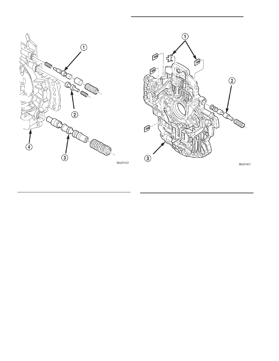
(3) Lubricate the oil pump valves with Mopar®

ATF +4, type 9602, and install the valve, spring and
retainer into the appropriate oil pump valve body
bore (Fig. 91) (Fig. 92).

(4) Place the separator plate onto the oil pump

body (Fig. 90).

(5) Install the screws to hold the separator plate

onto the oil pump body (Fig. 90). Tighten the screws
to 4.5 N·m (40 in.lbs.).

(6) Position the oil pump cover onto the locating

dowels (Fig. 89).

(7) Seat the two oil pump halves together and

install all bolts finger tight.

(8) Torque all bolts down slowly starting in the

center and working outward. The correct torque is
4.5 N·m (40 in.lbs.).

(9) Verify that the oil pump gears rotate freely and

smoothly.

(10) Position the reaction shaft support into the oil

pump (Fig. 89).

Fig. 91 Oil Pump Valve Body

1 - T/C REGULATOR VALVE
2 - T/C LIMIT VALVE
3 - REGULATOR VALVE
4 - OIL PUMP VALVE BODY

Fig. 92 T/C Switch Valve

1 - RETAINER
2 - T/C SWITCH VALVE
3 - OIL PUMP VALVE BODY

21 - 512

AUTOMATIC TRANSMISSION - 45RFE

AN

OIL PUMP (Continued)

(11) Install and torque the bolts to hold the reac-

tion shaft support to the oil pump (Fig. 89). The cor-
rect torque is 12 N·m (105 in.lbs.).

OIL PUMP FRONT SEAL

REMOVAL

(1) Remove transmission from the vehicle.
(2) Remove the torque converter from the trans-

mission.

(3) Using a screw mounted in a slide hammer,

remove the oil pump front seal.

INSTALLATION

(1) Clean seal bore of the oil pump of any residue

or particles from the original seal.

(2) Install new oil seal in the oil pump housing

using Seal Installer C-3860-A (Fig. 93).

OUTPUT SPEED SENSOR

DESCRIPTION

The Input and Output Speed Sensors are two-wire

magnetic pickup devices that generate AC signals as
rotation occurs. They are mounted in the left side of
the transmission case and are considered primary
inputs to the Transmission Control Module (TCM).

OPERATION

The Input Speed Sensor provides information on

how fast the input shaft is rotating. As the teeth of
the input clutch hub pass by the sensor coil, an AC

voltage is generated and sent to the TCM. The TCM
interprets this information as input shaft rpm.

The Output Speed Sensor generates an AC signal

in a similar fashion, though its coil is excited by rota-
tion of the rear planetary carrier lugs. The TCM
interprets this information as output shaft rpm.

The TCM compares the input and output speed

signals to determine the following:

• Transmission gear ratio

• Speed ratio error detection

• CVI calculation
The TCM also compares the input speed signal and

the engine speed signal to determine the following:

• Torque converter clutch slippage

• Torque converter element speed ratio

REMOVAL

(1) Raise vehicle.
(2) Place a suitable fluid catch pan under the

transmission.

(3) Remove the wiring connector from the output

speed sensor (Fig. 94).

(4) Remove the bolt holding the output speed sen-

sor to the transmission case.

(5) Remove the output speed sensor from the

transmission case.

INSTALLATION

(1) Install the output speed sensor into the trans-

mission case.

(2) Install the bolt to hold the output speed sensor

into the transmission case. Tighten the bolt to 11.9
N·m (105 in.lbs.).

Fig. 93 Install Oil Pump Front Seal

1 - TOOL C-3860-A

Fig. 94 Output Speed Sensor

1 - OUTPUT SPEED SENSOR
2 - LINE PRESSURE SENSOR
3 - INPUT SPEED SENSOR

AN

AUTOMATIC TRANSMISSION - 45RFE

21 - 513

OIL PUMP (Continued)

(3) Install the wiring connector onto the output

speed sensor

(4) Verify the transmission fluid level. Add fluid as

necessary.

(5) Lower vehicle.

OVERDRIVE SWITCH

DESCRIPTION

The overdrive OFF (control) switch is located in

the shift lever arm (Fig. 95). The switch is a momen-
tary contact device that signals the PCM to toggle
current status of the overdrive function.

OPERATION

At key-on, overdrive operation is allowed. Pressing

the switch once causes the overdrive OFF mode to be
entered and the overdrive OFF switch lamp to be
illuminated. Pressing the switch a second time
causes normal overdrive operation to be restored and
the overdrive lamp to be turned off. The overdrive
OFF mode defaults to ON after the ignition switch is
cycled OFF and ON. The normal position for the con-
trol switch is the ON position. The switch must be in
this position to energize the solenoid and allow a 3-4
upshift. The control switch indicator light illuminates
only when the overdrive switch is turned to the OFF
position, or when illuminated by the transmission
control module.

REMOVAL

(1) Using a plastic trim tool, remove the overdrive

off switch retainer from the shift lever (Fig. 96).

(2) Pull the switch outwards to release it from the

connector in the lever (Fig. 97)

Fig. 95 Overdrive Off Switch

Fig. 96 Overdrive Off Switch Retainer

1 - GEAR SHIFT LEVER
2 - OVERDRIVE OFF SWITCH RETAINER
3 - PLASTIC TRIM TOOL

Fig. 97 Remove the Overdrive Off Switch

1 - GEAR SHIFT LEVER
2 - OVERDRIVE OFF SWITCH

21 - 514

AUTOMATIC TRANSMISSION - 45RFE

AN

OUTPUT SPEED SENSOR (Continued)

INSTALLATION

NOTE: There is enough slack in the wire to pull out
the connector from the lever.

(1) Pull the connector out of the lever just enough

to grasp it.

CAUTION: Be careful not to bend the pins on the
overdrive off switch. Use care when installing the
switch, as it is not indexed, and can be accidentally
installed incorrectly.

(2) Install the overdrive off switch into the connec-

tor (Fig. 98)

(3) Push the overdrive off switch and wiring into

the shift lever.

(4) Install the overdrive off switch retainer onto

the shift lever.

PISTONS

DESCRIPTION

There are several sizes and types of pistons used in

an automatic transmission. Some pistons are used to
apply clutches, while others are used to apply bands.
They all have in common the fact that they are
round or circular in shape, located within a smooth
walled cylinder, which is closed at one end and con-
verts fluid pressure into mechanical movement. The
fluid pressure exerted on the piston is contained
within the system through the use of piston rings or
seals.

OPERATION

The principal which makes this operation possible

is known as Pascal’s Law. Pascal’s Law can be stated
as: “Pressure on a confined fluid is transmitted
equally in all directions and acts with equal force on
equal areas.”

PRESSURE

Pressure (Fig. 99) is nothing more than force (lbs.)

divided by area (in or ft.), or force per unit area.
Given a 100 lb. block and an area of 100 sq. in. on
the floor, the pressure exerted by the block is: 100
lbs. 100 in or 1 pound per square inch, or PSI as it is
commonly referred to.

PRESSURE ON A CONFINED FLUID

Pressure is exerted on a confined fluid (Fig. 100)

by applying a force to some given area in contact
with the fluid. A good example of this is a cylinder
filled with fluid and equipped with a piston that is
closely fitted to the cylinder wall. If a force is applied
to the piston, pressure will be developed in the fluid.
Of course, no pressure will be created if the fluid is
not confined. It will simply “leak” past the piston.
There must be a resistance to flow in order to create
pressure. Piston sealing is extremely important in
hydraulic operation. Several kinds of seals are used
to accomplish this within a transmission. These
include but are not limited to O-rings, D-rings, lip
seals, sealing rings, or extremely close tolerances
between the piston and the cylinder wall. The force
exerted is downward (gravity), however, the principle
remains the same no matter which direction is taken.

Fig. 98 Install the Overdrive Off Switch

1 - GEAR SHIFT LEVER
2 - OVERDRIVE OFF SWITCH WIRING CONNECTOR
3 - OVERDRIVE OFF SWITCH

Fig. 99 Force and Pressure Relationship

AN

AUTOMATIC TRANSMISSION - 45RFE

21 - 515

OVERDRIVE SWITCH (Continued)


Content   ..  715  716  717  718   ..