Dodge Dakota (R1). Manual - part 716


  Index      Dodge     Dodge Dakota (R1) - service repair manual 2000 year


Search            


Content   ..  714  715  716  717   ..


Dodge Dakota (R1). Manual - part 716


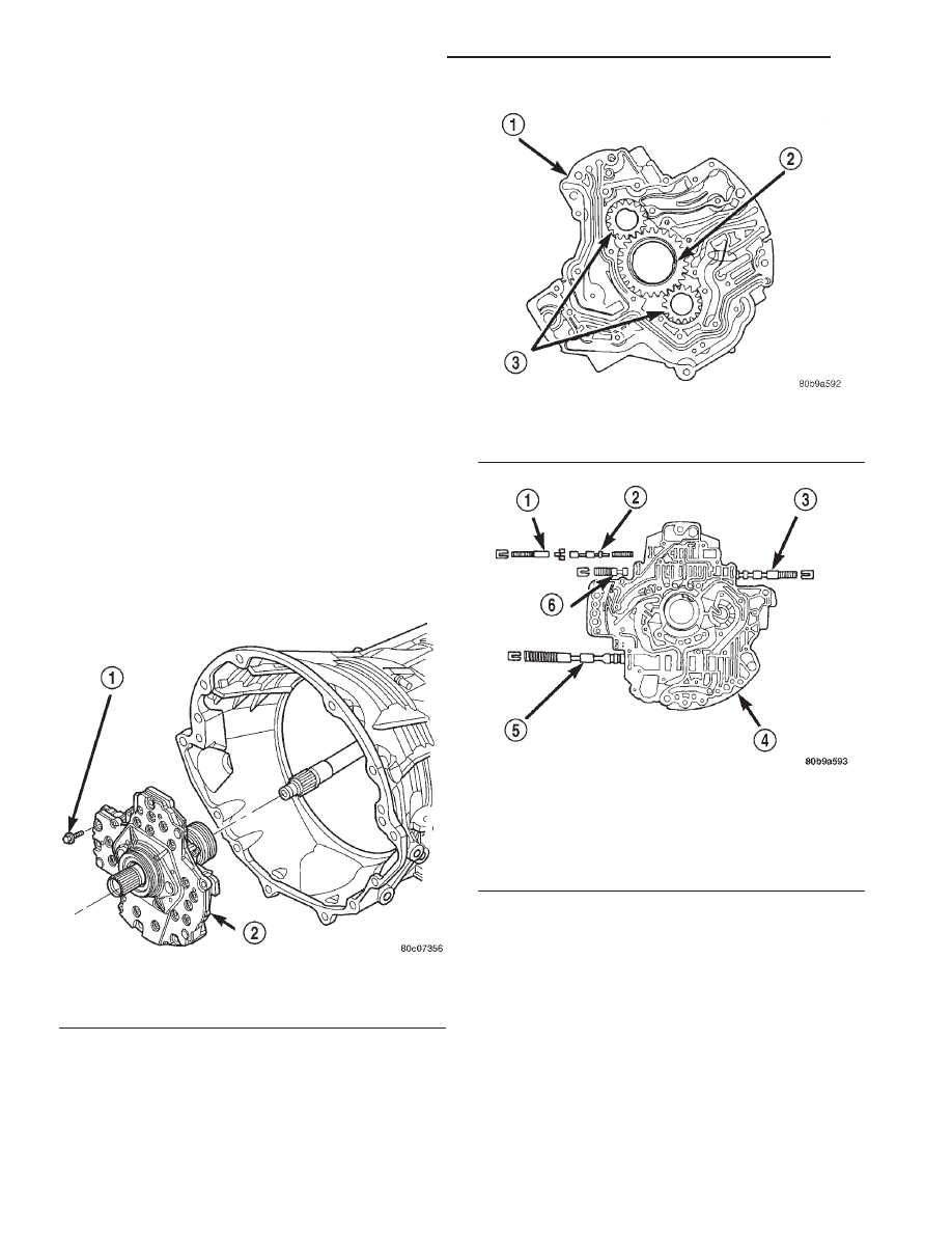
plate is directional and must be installed with the
flat side down.

(12) Install the low/reverse clutch pack snap-ring

(Fig. 82). The snap-ring is selectable and should be
chosen to give the correct clutch pack clearance.

(13) Measure the low/reverse clutch pack clearance

and adjust as necessary. The correct clutch clearance
is 1.14-1.91 mm (0.045-0.075 in.).

(14) Install the overrunning clutch into the low/re-

verse clutch retainer making sure that the index
splines are aligned with the retainer.

(15) Install the overrunning clutch inner snap-

ring.

OIL PUMP

DESCRIPTION

The oil pump (Fig. 85) is located at the front of the

transmission inside the bell housing and behind the
transmission front cover. The oil pump consists of
two independent pumps (Fig. 86), a number of valves
(Fig. 87), a front seal (Fig. 88), and a bolt on reaction
shaft. The converter clutch switch and regulator
valves, pressure regulator valve, and converter pres-
sure limit valve are all located in the oil pump hous-
ing.

OPERATION

As the torque converter rotates, the converter hub

rotates the oil pump drive gear. As the drive gear
rotates both driven gears, the clearance between the
gear teeth increases in the crescent area, and creates
a suction at the inlet side of the pump. This suction

draws fluid through the pump inlet from the oil pan.
As the clearance between the gear teeth in the cres-
cent area decreases, it forces pressurized fluid into
the pump outlet and to the oil pump valves.

At low speeds, both pumps supply fluid to the

transmission. As the speed of the torque converter
increases,

the

pressure

output

of

both

pumps

increases until the primary pump pressure reaches
the point where it can close off the check valve
located between the two pumps. When the check
valve is closed, the secondary pump is shut down and
the primary pump supplies all the fluid to the trans-
mission.

Fig. 85 Oil Pump

1 - OIL PUMP TO CASE BOLT (6)
2 - OIL PUMP

Fig. 86 Oil Pump Gears

1 - PUMP BODY
2 - DRIVE GEAR
3 - DRIVEN GEARS

Fig. 87 Oil Pump Valves

1 - TORQUE CONVERTER CLUTCH ACCUMULATOR VALVE
2 - TORQUE CONVERTER CLUTCH CONTROL VALVE
3 - TORQUE CONVERTER CLUTCH SWITCH VALVE
4 - PUMP COVER
5 - PRESSURE REGULATOR VALVE
6 - TORQUE CONVERTER CLUTCH LIMIT VALVE

21 - 508

AUTOMATIC TRANSMISSION - 45RFE

AN

LOW/REVERSE CLUTCH (Continued)

CONVERTER CLUTCH SWITCH VALVE

The converter clutch switch valve is used to control

the hydraulic pressure supplied to the front (OFF)
side of the torque converter clutch.

CONVERTER CLUTCH REGULATOR VALVE

The converter clutch regulator valve is used to con-

trol the hydraulic pressure supplied to the back (ON)
side of the torque converter clutch.

TORQUE CONVERTER LIMIT VALVE

The torque converter limit valve serves to limit the

available line pressure to the torque converter clutch
to approximately 120 psi.

STANDARD PROCEDURE - OIL PUMP VOLUME
CHECK

Measuring the oil pump output volume will deter-

mine if sufficient oil flow to the transmission oil
cooler exists, and whether or not an internal trans-
mission failure is present.

Verify that the transmission fluid is at the proper

level. Refer to the Fluid Level Check procedure in
this section. If necessary, fill the transmission to the
proper level with Mopar® ATF +4, type 9602, Auto-
matic Transmission Fluid.

(1) Disconnect the To cooler line at the cooler

inlet and place a collecting container under the dis-
connected line.

Fig. 88 Oil Pump Reaction Shaft

1 - PUMP HOUSING

4 - SEAL RING (5)

2 - SEAL

5 - REACTION SHAFT SUPPORT

3 - OIL FILTER SEAL

6 - VALVE BODY

AN

AUTOMATIC TRANSMISSION - 45RFE

21 - 509

OIL PUMP (Continued)

CAUTION: With the fluid set at the proper level,
fluid collection should not exceed (1) quart or inter-
nal damage to the transmission may occur.

(2) Run the engine at 1800 rpm, with the shift

selector in neutral. Verify that the transmission fluid
temperature is below 104.5° C (220° F) for this test.

(3) If one quart of transmission fluid is collected in

the container in 30 seconds or less, oil pump flow vol-
ume is within acceptable limits. If fluid flow is inter-
mittent, or it takes more than 30 seconds to collect
one quart of fluid, refer to the Hydraulic Pressure
tests in this section for further diagnosis.

(4) Re-connect the To cooler line to the transmis-

sion cooler inlet.

(5) Refill the transmission to proper level.

DISASSEMBLY

(1) Remove the bolts holding the reaction shaft

support to the oil pump (Fig. 89).

(2) Remove the reaction shaft support from the oil

pump (Fig. 89).

(3) Remove all bolts holding the oil pump halves

together (Fig. 89).

(4) Using suitable prying tools, separate the oil

pump sections by inserting the tools in the supplied
areas and prying the halves apart.

NOTE: The oil pump halves are aligned to each
other through the use of two dowels. Be sure to pry
upward evenly to prevent damage to the oil pump
components.

Fig. 89 Oil Pump Assembly

1 - PUMP HOUSING

4 - SEAL RING (5)

2 - SEAL

5 - REACTION SHAFT SUPPORT

3 - OIL FILTER SEAL

6 - VALVE BODY

21 - 510

AUTOMATIC TRANSMISSION - 45RFE

AN

OIL PUMP (Continued)

(5) Remove the screws holding the separator plate

onto the oil pump body (Fig. 90).

(6) Remove the separator plate from the oil pump

body (Fig. 90).

(7) Mark all gears for location. The gears are

select fit and if the oil pump is to be reused, the
gears must be returned to their original locations.

(8) Remove the oil pump gears from the oil pump

case (Fig. 90).

(9) Remove the oil pump valve retainers and asso-

ciated valve and spring one at a time (Fig. 91) (Fig.
92). Mark the combination of components as a group
and tag them as to the location from which they were
removed.

CLEANING

Clean pump and support components with solvent

and dry them with compressed air.

INSPECTION

Check condition of the seal rings and thrust

washer on the reaction shaft support. The seal rings
do not need to be replaced unless cracked, broken, or
severely worn.

Inspect the pump and support components. Replace

the pump or support if the seal ring grooves or
machined surfaces are worn, scored, pitted, or dam-
aged. Replace the pump gears if pitted, worn
chipped, or damaged.

Fig. 90 Oil Pump Housing and Gears

1 - SEPARATOR PLATE

5 - DOWEL (2)

2 - DRIVEN GEAR (2)

6 - DRIVE GEAR

3 - CHECK VALVE

7 - SCREW

4 - PUMP HOUSING

AN

AUTOMATIC TRANSMISSION - 45RFE

21 - 511

OIL PUMP (Continued)


Content   ..  714  715  716  717   ..