Dodge Dakota (R1). Manual - part 714


  Index      Dodge     Dodge Dakota (R1) - service repair manual 2000 year


Search            


Content   ..  712  713  714  715   ..


Dodge Dakota (R1). Manual - part 714


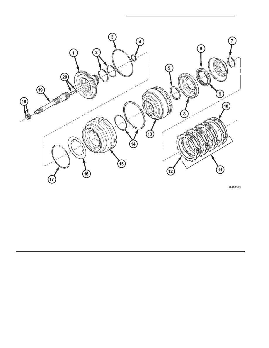
Fig. 71 Input Clutch Assembly - Part II

1 - INPUT CLUTCH HUB

11 - UD CLUTCH

2 - O-RING SEALS

12 - PLATE

3 - SEAL

13 - CLUTCH RETAINER

4 - SNAP-RING

14 - SEAL

5 - SNAP-RING

15 - OD/REV PISTON

6 - UD BALANCE PISTON

16 - BELLEVILLE SPRING

7 - SNAP-RING

17 - SNAP-RING

8 - UD PISTON

18 - SEAL RINGS

9 - SPRING

19 - INPUT SHAFT

10 - DISC

20 - LUBRICATION CHECK VALVE AND SNAP-RING

21 - 500

AUTOMATIC TRANSMISSION - 45RFE

AN

INPUT CLUTCH ASSEMBLY (Continued)

(7) Install Piston Guides 8504 into the input clutch

retainer (Fig. 72) and onto the input clutch hub to
guide the inner and outer underdrive piston seals
into position.

(8) Install the underdrive piston into the input

clutch retainer and over the input clutch hub (Fig.
71).

(9) Install the UD/OD balance piston return spring

pack into the input clutch retainer.

(10) Install Piston Guide 8252 into the input

clutch retainer (Fig. 73) to guide the UD/OD balance
piston seal into position inside the underdrive piston.

(11) Install the UD/OD balance piston into the

input clutch retainer and the underdrive piston.

(12) Using Spring Compressor 8251, compress the

UD/OD return spring pack and secure the piston in
place with the snap-ring (Fig. 74).

(13) Install the underdrive clutch pack into the

input clutch retainer (Fig. 71).

(14) Install the UD/OD reaction plate lower flat

snap-ring (Fig. 75). The correct snap-ring can be
identified by the two tabbed ears.

(15) Install the UD/OD reaction plate into the

input clutch retainer. The reaction plate is to be
installed with the big step down.

(16) Install

the

UD/OD

reaction

plate

upper

tapered snap-ring with tapered side up.

Fig. 72 Install Underdrive Piston Using Tool 8504

1 - TOOL 8504

Fig. 73 Install Balance Piston Using Tool 8252

1 - TOOL 8252

Fig. 74 Compressing UD/OD Balance Piston Using

Tool 8251

1 - PRESS
2 - TOOL 8251
3 - BALANCE PISTON

AN

AUTOMATIC TRANSMISSION - 45RFE

21 - 501

INPUT CLUTCH ASSEMBLY (Continued)

Fig. 75 Input Clutch Assembly - Part I

1 - BEARING NUMBER 3

10 - SNAP-RING (SELECT)

2 - OD HUB/SHAFT

11 - PLATE

3 - SNAP-RING (WAVE)

12 - DISC

4 - REV/OD REACTION PLATE

13 - OD CLUTCH

5 - BEARING NUMBER 4

14 - SNAP-RING (TAPERED)

6 - SNAP-RING (FLAT)

15 - UD/OD REACTION PLATE

7 - REVERSE HUB/SHAFT

16 - SNAP-RING (FLAT)

8 - REVERSE CLUTCH

17 - UD HUB/SHAFT

9 - REVERSE REACTION PLATE

18 - BEARING NUMBER 2

21 - 502

AUTOMATIC TRANSMISSION - 45RFE

AN

INPUT CLUTCH ASSEMBLY (Continued)

(17) Install the input clutch assembly into Input

Clutch Pressure Fixture 8260 (Fig. 76). Mount a dial
indicator to the assembly, push down on the clutch
discs and zero the indicator against the underdrive
clutch discs (Fig. 77). Apply 20 psi of air pressure to
the underdrive clutch and record the dial indicator
reading. Measure and record UD clutch pack mea-
surement in four (4) places, 90° apart. Take average
of four measurements and compare with UD clutch
pack clearance specification. The correct clutch clear-
ance is 0.76-1.16 mm (0.030-0.063 in.). The reaction
plate is not selective. If the clutch clearance is not
within specification, replace the reaction plate along
with all the friction and steel discs.

(18) Install the overdrive clutch pack into the

input clutch retainer (Fig. 75). The overdrive steel
separator plates can be identified by the lack of the
half-moon cuts in the locating tabs.

(19) Install the overdrive clutch wavy snap-ring

with the two tabbed ears into the input clutch
retainer.

(20) Install the OD/reverse reaction plate into the

input clutch retainer. The reaction plate is non-direc-
tional (Fig. 75).

(21) Install the OD/reverse reaction plate flat

snap-ring into the input clutch retainer.

(22) Mount a dial indicator to the assembly and

zero the indicator against the OD/reverse reaction
plate (Fig. 78). Apply 20 psi of air pressure to the

overdrive clutch and record the dial indicator read-
ing. Measure and record OD clutch pack measure-
ment in four (4) places, 90° apart. Take average of
four measurements and compare with OD clutch
pack clearance specification.Verify that the clutch
clearance is 1.016-1.65 mm (0.040-0.065 in.). The
reaction plate is not selective. If the clutch clearance
is not within specification, replace the reaction plate
along with all the friction and steel discs.

Fig. 76 Input Clutch Assembly Mounted on Tool

8260

1 - INPUT CLUTCH ASSEMBLY
2 - TOOL 8260

Fig. 77 Measuring UD Clutch Clearance

1 - TOOL C-3339
2 - UNDERDRIVE CLUTCH PACK

Fig. 78 Measuring OD Clutch Clearance

1 - TOOL C-3339
2 - OD/REV REACTION PLATE

AN

AUTOMATIC TRANSMISSION - 45RFE

21 - 503

INPUT CLUTCH ASSEMBLY (Continued)


Content   ..  712  713  714  715   ..