Dodge Dakota (R1). Manual - part 689
OPERATION
NOTE: Refer to the Hydraulic Schematics for a
visual aid in determining valve location, operation
and design.
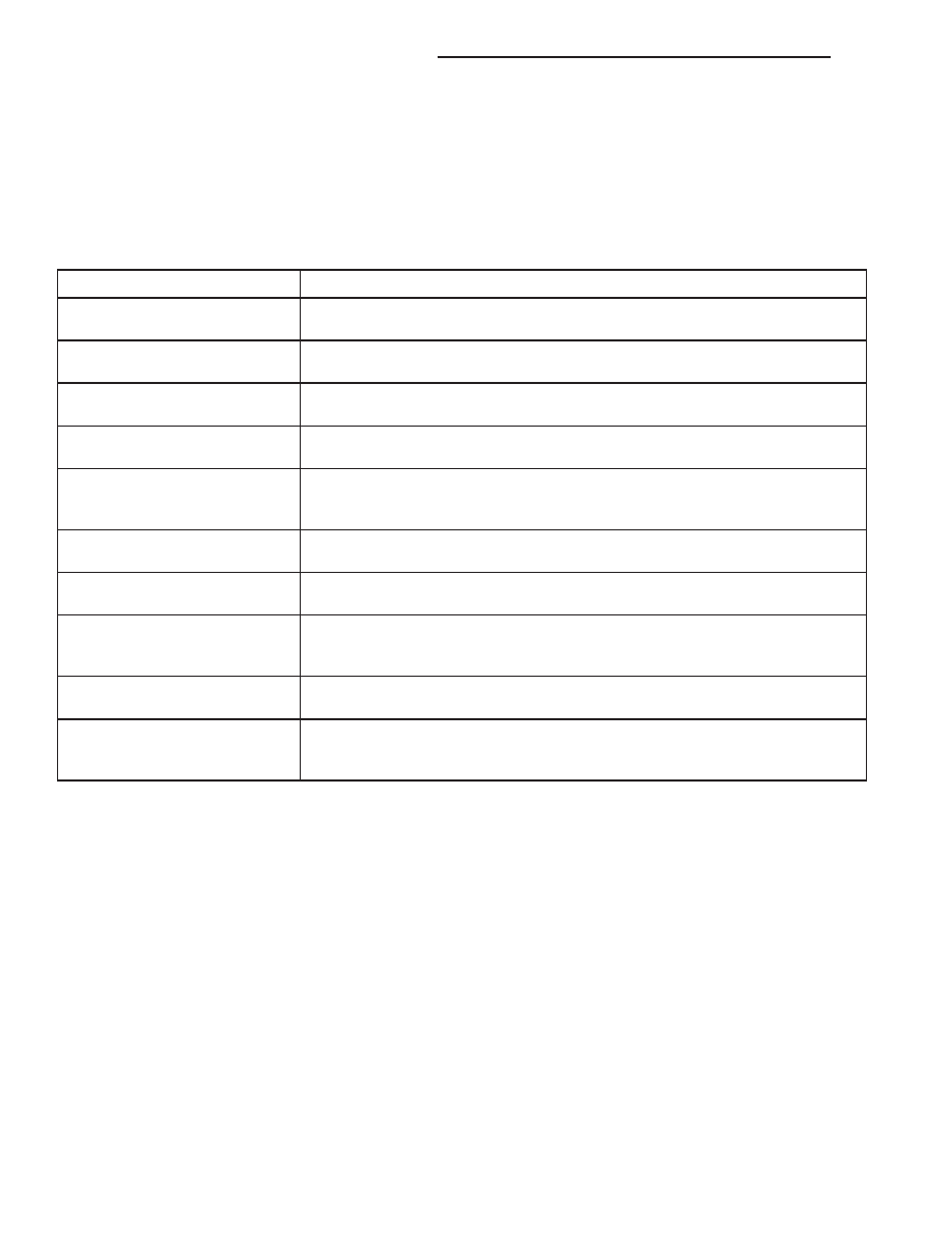
CHECK BALLS
CHECK BALL NUMBER
DESCRIPTION
1
Allows either the manual valve to put line pressure on the 1-2 governor plug or
the KD Valve to put WOT line pressure on the 1-2 governor plug.
2
Allows either the manual valve to put line pressure on the 2-3 governor plug or
the KD Valve to put WOT line pressure on the 2-3 governor plug.
3
Allows either the Reverse circuit or the 3rd gear circuit to pressurize the front
clutch.
4
Allows either the Manual Low circuit from the Manual Valve or the Reverse
from the Manual Valve circuit to pressurize the rear servo.
5
Directs line pressure to the spring end of the 2-3 shift valve in either Manual
Low or Manual 2nd, forcing the downshift to 2nd gear regardless of governor
pressure.
6
Provides a by-pass around the front servo orifice so that the servo can release
quickly.
7
Provides a by-pass around the rear clutch orifice so that the clutch can release
quickly.
8
Directs reverse line pressure through an orifice to the throttle valve eliminating
the extra leakage and insuring that Reverse line pressure pressure will be
sufficient.
9
Provides a by-pass around the rear servo orifice so that the servo can release
quickly.
ECE (10)
Allows the lockup clutch to used at WOT in 3rd gear by putting line pressure
from the 3-4 Timing Valve on the interlock area of the 2-3 shift valve, thereby
preventing a 3rd gear Lock-up to 2nd gear kickdown.
REGULATOR VALVE
The pressure regulator valve is needed to control
the hydraulic pressure within the system and reduce
the amount of heat produced in the fluid. The pres-
sure regulator valve is located in the valve body near
the manual valve. The pressure regulator valve train
controls the maximum pressure in the lines by
metering the dumping of fluid back into the sump.
Regulated pressure is referred to as “line pressure.”
The regulator valve (Fig. 265) has a spring on one
end that pushes the valve to the left. This closes a
dump (vent) that is used to lower pressure. The clos-
ing of the dump will cause the oil pressure to
increase. Oil pressure on the opposite end of the
valve pushes the valve to the right, opening the
dump and lowering oil pressure. The result is spring
pressure working against oil pressure to maintain
the oil at specific pressures. With the engine run-
ning, fluid flows from the pump to the pressure reg-
ulator valve, manual valve, and the interconnected
circuits. As fluid is sent through passages to the reg-
ulator valve, the pressure pushes the valve to the
right against the large spring. It is also sent to the
reaction areas on the left side of the throttle pressure
plug and the line pressure plug. With the gear selec-
tor in the PARK position, fluid recirculates through
the regulator and manual valves back to the sump.
Meanwhile, the torque converter is filled slowly. In
all other gear positions (Fig. 266), fluid flows
between two right side lands to the switch valve and
torque converter. At low pump speeds, the flow is
controlled by the pressure valve groove to reduce
pressure to the torque converter. After the torque
converter and switch valve fill with fluid, the switch
valve becomes the controlling metering device for
torque converter pressure. The regulator valve then
begins to control the line pressure for the other
transmission circuits. The balance of the fluid pres-
21 - 400
AUTOMATIC TRANSMISSION - 46RE
AN
VALVE BODY (Continued)