Dodge Dakota (R1). Manual - part 687


  Index      Dodge     Dodge Dakota (R1) - service repair manual 2000 year


Search            


Content   ..  685  686  687  688   ..


Dodge Dakota (R1). Manual - part 687


Mechanical

State

Electronic Display

(Ignition

Unlocked)

Electronic Display

(Ignition On)

Indicated Gear Position

Transmission Status

Column Shifter
Position

P

P

P

Vehicle is in PARK with the
pawl engaged.

In the PARK gate.

R

The PARK pawl is disengaged
and the vehicle is free to roll,
but REVERSE is not engaged.

Between the PARK
and REVERSE
gates.

R

R

R

The transmission is
hydraulically in REVERSE.

In the REVERSE
gate.

N

The transmission is
transitioning between
REVERSE and NEUTRAL.

Between the
REVERSE and
NEUTRAL gates.

N

N

N

The vehicle is in NEUTRAL.

In the NEUTRAL
gate.

N

The transmission is
transitioning between
NEUTRAL and DRIVE, but is
not in DRIVE.

Between the
NEUTRAL and
DRIVE gates.

D

D

D

The transmission is
hydraulically in DRIVE.

In the DRIVE gate,

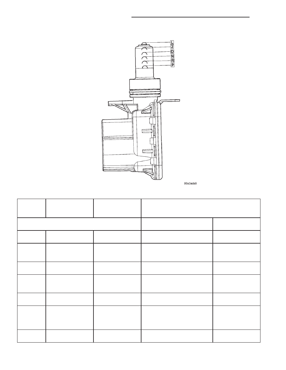
Fig. 253 Transmission Range Sensor Linear Movement

21 - 392

AUTOMATIC TRANSMISSION - 46RE

AN

TRANSMISSION RANGE SENSOR (Continued)

Mechanical

State

Electronic Display

(Ignition

Unlocked)

Electronic Display

(Ignition On)

Indicated Gear Position

Transmission Status

Column Shifter
Position

2

2

2

The transmission is
hydraulically in Manual
SECOND.

In the SECOND
gate.

1

1

1

The transmission is
hydraulically in Manual FIRST.

In the FIRST gate.

DIAGNOSIS AND TESTING - TRANSMISSION
RANGE SENSOR (TRS)

NOTE: For all circuit identification in the following
steps, Refer to the appropriate Wiring Information.

(1) Raise vehicle on suitable hoist.
(2) Disconnect the vehicle’s shift cable from the

manual lever.

(3) With the manual lever in the PARK position

(the PARK position is with the manual lever moved
to the full rearward position), measure the resistance
between the Park/Neutral Position Sense pin of the
TRS and the transmission case. The resistance
should be less than 5 ohms.

(4) With the manual lever in the NEUTRAL posi-

tion (the NEUTRAL position is with the manual
lever moved two detents forward of the full rearward
position), measure the resistance between the Park/
Neutral Position Sense pin of the TRS and the trans-
mission case. The resistance should be less than 5
ohms.

(5) If the resistance is greater than 5 ohms in

either of the previous steps, check for a dirty contact
between the tip of the TRS rod and the valve body
manual lever. If the contact is OK, replace the TRS.

(6) With the manual lever in the REVERSE posi-

tion (the REVERSE position is with the manual lever
moved one detent forward of the full rearward posi-
tion), measure the resistance between the Fused
Ignition Switch Output and the Back-up Lamp feed
pins of the TRS. The resistance should be less than 5
ohms. If the resistance is greater than 5 ohms,
replace the TRS.

(7) With the manual lever in the PARK position

(the PARK position is with the manual lever moved
to the full rearward position), measure the resistance
between the Cluster Resistance Signal and the Clus-

ter Signal Return pins of the TRS. The resistance
should be 522.2 ohms. If the resistance is not correct,
replace the TRS.

(8) With the manual lever in the REVERSE posi-

tion (the REVERSE position is with the manual lever
moved one detent forward of the full rearward posi-
tion), measure the resistance between the Cluster
Resistance Signal and the Cluster Signal Return pins
of the TRS. The resistance should be 206.2 ohms. If
the resistance is not correct, replace the TRS.

(9) With the manual lever in the NEUTRAL posi-

tion (the NEUTRAL position is with the manual
lever moved two detents forward of the full rearward
position), measure the resistance between the Cluster
Resistance Signal and the Cluster Signal Return pins
of the TRS. The resistance should be 108.6 ohms. If
the resistance is not correct, replace the TRS.

(10) With the manual lever in the DRIVE position

(the DRIVE position is with the manual lever moved
three detents forward of the full rearward position),
measure the resistance between the Cluster Resis-
tance Signal and the Cluster Signal Return pins of
the TRS. The resistance should be 59.9 ohms. If the
resistance is not correct, replace the TRS.

(11) With the manual lever in the SECOND posi-

tion (the SECOND position is with the manual lever
moved one detent rearward of the full forward posi-
tion), measure the resistance between the Fused
Ignition Switch Output and the Back-up Lamp feed
pins of the TRS. The resistance should be 31.9 ohms.
If the resistance is not correct, replace the TRS.

(12) With the manual lever in the LOW position

(the LOW position is with the manual lever moved to
the full forward position), measure the resistance
between the Fused Ignition Switch Output and the
Back-up Lamp feed pins of the TRS. The resistance
should be 13.7 ohms. If the resistance is not correct,
replace the TRS.

AN

AUTOMATIC TRANSMISSION - 46RE

21 - 393

TRANSMISSION RANGE SENSOR (Continued)

REMOVAL

(1) Raise vehicle and position drain pan under the

transmission range sensor (TRS).

(2) Move the transmission manual lever to the

manual LOW position. The manual LOW position is
with the manual lever in the forward-most detent.

(3) Disengage the wiring connector from the TRS.
(4) Remove the two screws holding the TRS to the

TRS mounting bracket.

(5) Remove the TRS (Fig. 254) from the TRS

mounting bracket by pulling it straight out of the
bracket.

(6) Loosen the TRS mounting bracket in the trans-

mission case using Adapter 8581 (Fig. 255).

(7) Remove the TRS mounting bracket (Fig. 256)

from the transmission case.

INSTALLATION

(1) Move the transmission manual shaft lever to

the manual LOW position.

(2) Install the TRS mounting bracket into the

transmission case. Using Adapter 8581 (Fig. 257),
tighten the mounting bracket to 34 N·m (300 in.lbs.).

(3) Install the TRS (Fig. 258) into the mounting

bracket with the wiring connector facing the front of
the transmission.

Fig. 254 Remove Transmission Range Sensor

1 - SOLENOID CASE CONNECTOR
2 - TRS MOUNTING BRACKET
3 - TRANSMISSION RANGE SENSOR

Fig. 255 Loosen the TRS Mounting Bracket

1 - SOLENOID CASE CONNECTOR
2 - TRS MOUNTING BRACKET
3 - ADAPTER 8581

Fig. 256 Remove TRS Mounting Bracket

1 - SOLENOID CASE CONNECTOR
2 - TRS MOUNTING BRACKET

Fig. 257 Tighten the TRS Mounting Bracket

1 - SOLENOID CASE CONNECTOR
2 - TRS MOUNTING BRACKET
3 - ADAPTER 8581

21 - 394

AUTOMATIC TRANSMISSION - 46RE

AN

TRANSMISSION RANGE SENSOR (Continued)

(4) Install the two screws to hold the TRS to the

mounting bracket. Tighten the screws to 3.4 N·m (30
in.lbs.).

(5) Verify proper sensor operation (Fig. 259).

(6) Move the transmission manual shaft lever to

the PARK position.

(7) Connect TRS wiring connector to the TRS and

lower vehicle.

(8) Refill the transmission fluid to the correct

level.

TRANSMISSION
TEMPERATURE SENSOR

DESCRIPTION

Transmission fluid temperature readings are sup-

plied to the transmission control module by the ther-
mistor (Fig. 260). The temperature readings are used
to control engagement of the fourth gear overdrive
clutch, the converter clutch, and governor pressure.
Normal resistance value for the thermistor at room
temperature is approximately 1000 ohms.

The thermistor is part of the governor pressure

sensor assembly and is immersed in transmission
fluid at all times.

OPERATION

The PCM prevents engagement of the converter

clutch and overdrive clutch, when fluid temperature
is below approximately 10°C (50°F).

If fluid temperature exceeds 126°C (260°F), the

PCM causes a 4-3 downshift and engage the con-
verter clutch. Engagement is according to the third
gear converter clutch engagement schedule.

The overdrive OFF lamp in the instrument panel

illuminates when the shift back to third occurs. The
transmission will not allow fourth gear operation
until fluid temperature decreases to approximately
110°C (230°F).

Fig. 258 Remove Transmission Range Sensor

1 - SOLENOID CASE CONNECTOR
2 - TRS MOUNTING BRACKET
3 - TRANSMISSION RANGE SENSOR

Fig. 259 Transmission Range Sensor Operation

1 - NEUTRAL CONTACT
2 - MANUAL LEVER AND SENSOR PLUNGER IN REVERSE
POSITION
3 - PARK CONTACT
4 - TRANSMISSION RANGE SENSOR

Fig. 260 Governor Pressure Sensor

1 - GOVERNOR BODY
2 - GOVERNOR PRESSURE SENSOR/TRANSMISSION FLUID
TEMPERATURE THERMISTOR

AN

AUTOMATIC TRANSMISSION - 46RE

21 - 395

TRANSMISSION RANGE SENSOR (Continued)


Content   ..  685  686  687  688   ..