Dodge Dakota (R1). Manual - part 690


  Index      Dodge     Dodge Dakota (R1) - service repair manual 2000 year


Search            


Content   ..  688  689  690  691   ..


Dodge Dakota (R1). Manual - part 690


KICKDOWN VALVE

When the throttle valve is as far over to the left as

it can go, the maximum line pressure possible will
enter the throttle pressure circuit. In this case, throt-
tle pressure will equal line pressure. With the kick-
down valve (Fig. 269) pushed into the bore as far as
it will go, fluid initially flows through the annular
groove of the 2-3 shift valve (which will be in the
direct drive position to the right).

After passing the annular groove, the fluid is

routed to the spring end of the 2-3 shift valve. Fluid
pressure reacting on the area of land #1 overcomes
governor pressure, downshifting the 2-3 shift valve
into the kickdown, or second gear stage of operation.
The valve is held in the kickdown position by throttle
pressure routed from a seated check ball (#2). Again,
if vehicle speed is low enough, throttle pressure will
also push the 1-2 shift valve left to seat its governor
plug, and downshift to drive breakaway.

KICKDOWN LIMIT VALVE

The purpose of the limit valve is to prevent a 3-2

downshift at higher speeds when a part-throttle
downshift is not desirable. At these higher speeds
only a full throttle 3-2 downshift will occur. At low
road speeds (Fig. 270) the limit valve does not come
into play and does not affect the downshifts. As the
vehicle’s speed increases (Fig. 271), the governor
pressure also increases. The increased governor pres-
sure acts on the reaction area of the bottom land of
the limit valve overcoming the spring force trying to
push the valve toward the bottom of its bore. This
pushes the valve upward against the spring and bot-
toms the valve against the top of the housing. With
the valve bottomed against the housing, the throttle
pressure supplied to the valve will be closed off by
the bottom land of the limit valve. When the supply
of throttle pressure has been shut off, the 3-2 part
throttle downshift plug becomes inoperative, because
no pressure is acting on its reaction area.

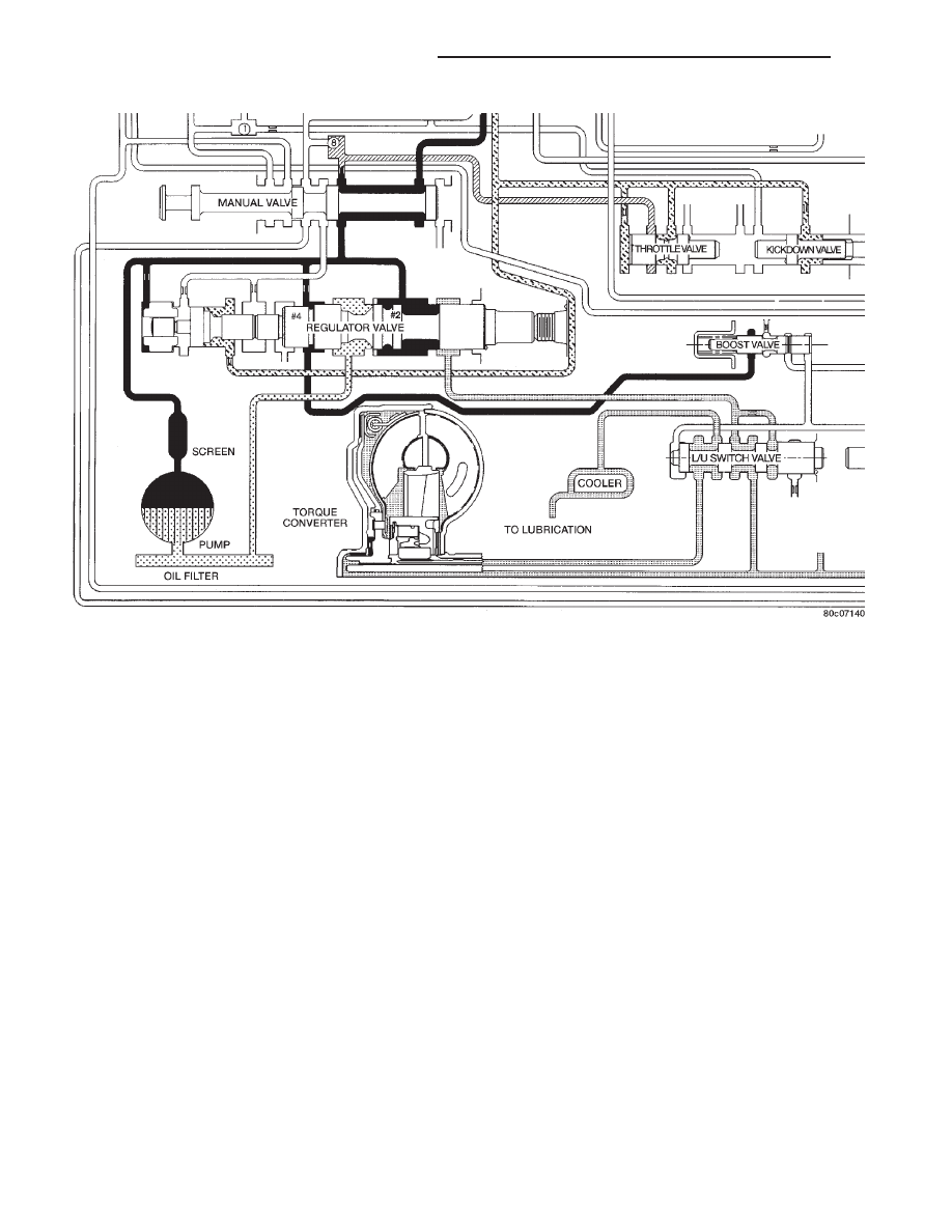
Fig. 268 Regulator Valve in REVERSE Position

21 - 404

AUTOMATIC TRANSMISSION - 46RE

AN

VALVE BODY (Continued)

Fig. 269 Kickdown Valve-Wide Open Throttle

Fig. 270 Kickdown Limit Valve-Low Speeds

AN

AUTOMATIC TRANSMISSION - 46RE

21 - 405

VALVE BODY (Continued)

1-2 SHIFT VALVE

The 1-2 shift valve assembly (Fig. 272), or mecha-

nism, consists of: the 1-2 shift valve, governor plug,
and a spring on the end of the valve. After the man-
ual valve has been placed into a forward gear range,
line pressure is directed to the 1-2 shift valve. As the
throttle is depressed, throttle pressure is applied to
the right side of the 1-2 shift valve assembly. With
throttle pressure applied to the right side of the
valve, there is now both spring pressure and throttle
pressure acting on the valve, holding it against the
governor plug. As the vehicle begins to move and
build speed, governor pressure is created and is
applied to the left of the valve at the governor plug.

When governor pressure builds to a point where it

can overcome the combined force of the spring and
throttle pressure on the other side of the valve, the
valve will begin to move over to the right. As the
valve moves to the right, the middle land of the valve
will close off the circuit supplying the throttle pres-
sure to the right side of the valve. When the throttle
pressure is closed off, the valve will move even far-
ther to the right, allowing line pressure to enter
another circuit and energize the front servo, applying
the front band (Fig. 273).

Fig. 271 Kickdown Limit Valve-High Speeds

Fig. 272 1-2 Shift Valve-Before Shift

21 - 406

AUTOMATIC TRANSMISSION - 46RE

AN

VALVE BODY (Continued)

The governor plug serves a dual purpose:
• It allows the shift valves to move either left or

right, allowing both upshifts and downshifts.

• When in a manual selection position, it will be

hydraulically “blocked” into position so no upshift can
occur.

The physical blocking of the upshift while in the

manual “1” position is accomplished by the directing
of line pressure between both lands of the governor
plug. The line pressure reacts against the larger land
of the plug, pushing the plug back against the end
plate overcoming governor pressure. With the combi-
nation of the line pressure and spring pressure, the
valve cannot move, preventing any upshift.

1-2 SHIFT CONTROL VALVE

It contains a valve with four lands and a spring. It

is used as both a “relay” and “balanced” valve.

The valve has two specific operations (Fig. 274):
• Aid in quality of the 1-2 upshift.

• Aid in the quality and timing of the 3-2 kick-

down ranges.

When the manual valve is set to the DRIVE position

and the transmission is in the first or second gear range,
1-2 shift control or “modulated throttle pressure” is sup-
plied to the middle of the accumulator piston by the 1-2
shift control valve. During the 1-2 upshift, this pressure
is used to control the kickdown servo apply pressure that
is needed to apply the kickdown and accumulator pis-
tons. Thus, the 1-2 shift point is “cushioned” and the
quality is improved. During a WOT kickdown, kickdown
pressure is applied between the kickdown valve and the
1-2 shift control valve. This additional pressure is
directed to the 1-2 shift control’s spring cavity, adding to
the spring load on the valve. The result of this increased
“modulated” throttle pressure is a firmer WOT upshift.

2-3 SHIFT VALVE

The 2-3 shift valve mechanism (Fig. 275) consists

of the 2-3 shift valve, governor plug and spring, and

a throttle plug. After the 1-2 shift valve has com-
pleted its operation and applied the front band, line
pressure is directed to the 2-3 shift valve through the
connecting passages from the 1-2 shift valve. The line
pressure will then dead–end at land #2 until the 2-3
valve is ready to make its shift. Now that the vehicle
is in motion and under acceleration, there is throttle
pressure being applied to the spring side of the valve
and between lands #3 and #4.

As vehicle speed increases, governor pressure

increases proportionately, until it becomes great
enough to overcome the combined throttle and spring
pressure on the right side of the valve. Since the
throttle pressure end of the 2-3 shift valve is larger
in diameter than the 1-2 shift valve, the 2-3 shift will
always happen at a greater speed than the 1-2 shift.
When this happens, the governor plug is forced
against the shift valve moving it to the right. The
shift valve causes land #4 to close the passage sup-
plying throttle pressure to the 2-3 shift valve. With-
out throttle pressure present in the circuit now, the
governor plug will push the valve over far enough to
bottom the valve in its bore. This allows land #2 to
direct line pressure to the front clutch.

After the shift (Fig. 276), line pressure is directed

to the land between the shift valve and the governor
plug, and to the release side of the kickdown servo.
This releases the front band and applies the front
clutch, shifting into third gear or direct drive. The
rear clutch remains applied, as it has been in the
other gears. During a manual “1” or manual “2” gear
selection, line pressure is sent between the two lands
of the 2-3 governor plug. This line pressure at the
governor plug locks the shift valve into the second
gear position, preventing an upshift into direct drive.
The theory for the blocking of the valve is the same
as that of the 1-2 shift valve.

Fig. 273 1-2 Shift Valve-After Shift

AN

AUTOMATIC TRANSMISSION - 46RE

21 - 407

VALVE BODY (Continued)


Content   ..  688  689  690  691   ..