Dodge Dakota (R1). Manual - part 650


  Index      Dodge     Dodge Dakota (R1) - service repair manual 2000 year


Search            


Content   ..  648  649  650  651   ..


Dodge Dakota (R1). Manual - part 650


3-4 ACCUMULATOR HOUSING

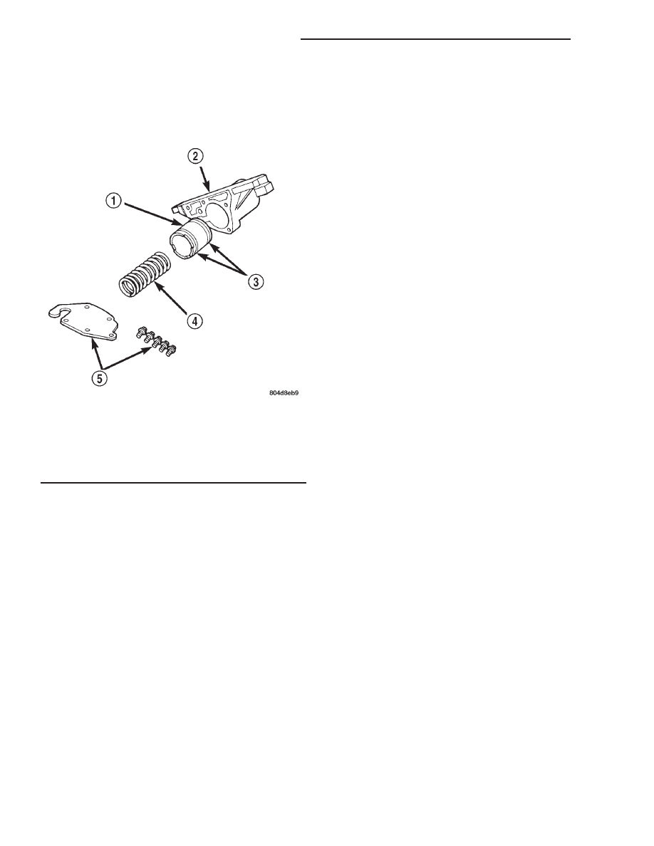
(1) Remove end plate from housing.
(2) Remove piston spring.
(3) Remove piston. Remove and discard piston

seals (Fig. 315).

CLEANING

Clean the valve housings, valves, plugs, springs,

and separator plates with a standard parts cleaning
solution only. Do not use gasoline, kerosene, or any
type of caustic solution.

Do not immerse any of the electrical components in

cleaning solution. Clean the governor solenoid and
sensor and the dual solenoid and harness assembly
by wiping them off with dry shop towels only.

Dry all except the electrical parts with compressed

air. Make sure all passages are clean and free from
obstructions. Do not use rags or shop towels to
dry or wipe off valve body components. Lint
from these materials can stick to valve body
parts, interfere with valve operation, and clog
filters and fluid passages.

Wipe the governor pressure sensor and solenoid

valve with dry, lint free shop towels only. The O-rings
on the sensor and solenoid valve are the only service-
able components. Be sure the vent ports in the sole-
noid valve are open and not blocked by dirt or debris.
Replace the valve and/or sensor only when DRB scan
tool diagnosis indicates this is necessary. Or, if either
part

has

sustained

physical

damage

(dented,

deformed, broken, etc.).

CAUTION: Do not turn the small screw at the end of
the solenoid valve for any reason. Turning the
screw in either direction will ruin solenoid calibra-
tion and result in solenoid failure. In addition, the
filter on the solenoid valve is NOT serviceable. Do
not try to remove the filter as this will damage the
valve housing.

INSPECTION

Inspect the throttle and manual valve levers and

shafts. Do not attempt to straighten a bent shaft or
correct a loose lever. Replace these components if
worn, bent, loose or damaged in any way.

Inspect all of the valve body mating surfaces for

scratches, nicks, burrs, or distortion. Use a straight-
edge to check surface flatness. Minor scratches may
be removed with crocus cloth using only very light
pressure.

Minor distortion of a valve body mating surface may

be corrected by smoothing the surface with a sheet of
crocus cloth. Position the crocus cloth on a surface
plate, sheet of plate glass or equally flat surface. If dis-
tortion is severe or any surfaces are heavily scored, the
valve body will have to be replaced.

CAUTION: Many of the valves and plugs, such as
the throttle valve, shuttle valve plug, 1-2 shift valve
and 1-2 governor plug, are made of coated alumi-
num. Aluminum components are identified by the
dark color of the special coating applied to the sur-
face (or by testing with a magnet). Do not sand alu-
minum valves or plugs under any circumstances.
This practice could damage the special coating
causing the valves/plugs to stick and bind.

Inspect the valves and plugs for scratches, burrs,

nicks, or scores. Minor surface scratches on steel
valves and plugs can be removed with crocus cloth but
do not round off the edges of the valve or plug
lands.
Maintaining sharpness of these edges is vitally
important. The edges prevent foreign matter from
lodging between the valves and plugs and the bore.

Fig. 315 Accumulator Housing Components

1 - ACCUMULATOR PISTON
2 - 3-4 ACCUMULATOR HOUSING
3 - TEFLON SEALS
4 - PISTON SPRING
5 - COVER PLATE AND SCREWS

21 - 244

AUTOMATIC TRANSMISSION - 42RE

AN

VALVE BODY (Continued)

Inspect all the valve and plug bores in the valve

body. Use a penlight to view the bore interiors.
Replace the valve body if any bores are distorted or
scored. Inspect all of the valve body springs. The
springs must be free of distortion, warpage or broken
coils.

Check the two separator plates for distortion or

damage of any kind. Inspect the upper housing,
lower housing, 3-4 accumulator housing, and transfer
plate carefully. Be sure all fluid passages are clean
and clear. Check condition of the upper housing and
transfer plate check balls as well. The check balls
and ball seats must not be worn or damaged.

Trial fit each valve and plug in its bore to check

freedom of operation. When clean and dry, the valves
and plugs should drop freely into the bores.

Valve body bores do not change dimensionally with

use. If the valve body functioned correctly when new,
it will continue to operate properly after cleaning and
inspection. It should not be necessary to replace a
valve body assembly unless it is damaged in han-
dling.

The only serviceable valve body components are

listed below. The remaining valve body components
are serviced only as part of a complete valve body
assembly. Serviceable parts are:

• dual solenoid and harness assembly

• solenoid gasket

• solenoid case connector O-rings and shoulder

bolt

• switch valve and spring

• pressure adjusting screw and bracket assembly

• throttle lever

• manual lever and shaft seal

• throttle lever shaft seal, washer, and E-clip

• fluid filter and screws

• detent ball and spring

• valve body screws

• governor pressure solenoid

• governor pressure sensor and retaining clip

• park lock rod and E-clip

ASSEMBLY

CAUTION: Do not force valves or plugs into place
during reassembly. If the valve body bores, valves
and plugs are free of distortion or burrs, the valve
body components should all slide into place easily.
In addition, do not overtighten the transfer plate
and valve body screws during reassembly. Over-
tightening can distort the housings resulting in
valve sticking, cross leakage and unsatisfactory
operation. Tighten valve body screws to recom-
mended torque only.

LOWER HOUSING

(1) Lubricate valves, springs, and the housing

valve and plug bores with clean transmission fluid
(Fig. 314).

(2) Install 3-4 timing valve spring and valve in

lower housing.

(3) Install 3-4 quick fill valve in lower housing.
(4) Install 3-4 quick fill valve spring and plug in

housing.

(5) Install timing valve end plate. Tighten end

plate screws to 4 N·m (35 in. lbs.) torque.

3-4 ACCUMULATOR

(1) Lubricate accumulator piston, seals and housing

piston bore with clean transmission fluid (Fig. 315).

(2) Install new seal rings on accumulator piston.
(3) Install piston and spring in housing.
(4) Install end plate on housing.

TRANSFER PLATE

(1) Install rear clutch and rear servo check balls in

transfer plate (Fig. 316).

(2) Install filter screen in upper housing separator

plate (Fig. 317).

(3) Align and position upper housing separator

plate on transfer plate (Fig. 318).

(4) Install brace plate (Fig. 318). Tighten brace

attaching screws to 4 N·m (35 in. lbs.) torque.

(5) Install remaining separator plate attaching

screws. Tighten screws to 4 N·m (35 in. lbs.) torque.

Fig. 316 Rear Clutch And Rear Servo Check Ball

Locations

1 - REAR CLUTCH CHECK BALL
2 - REAR SERVO CHECK BALL
3 - TRANSFER PLATE

AN

AUTOMATIC TRANSMISSION - 42RE

21 - 245

VALVE BODY (Continued)

UPPER AND LOWER HOUSING

(1) Position upper housing so internal passages

and check ball seats are facing upward. Then install
check balls in housing (Fig. 319). Eight check balls
are used. The single large check ball is approxi-
mately 8.7 mm (11/32 in.) diameter. The single small
check ball is approximately 4.8 mm (3/16 in.) in
diameter. The remaining 6 check balls are approxi-
mately 6.3 mm (1/4 in.) in diameter.

(2) Position assembled transfer plate and upper

housing separator plate on upper housing (Fig. 320).
Be sure filter screen is seated in proper housing recess.

(3) Install the ECE check ball into the transfer

plate (Fig. 306). The ECE check ball is approximately
4.8 mm (3/16 in.) in diameter.

(4) Position lower housing separator plate on

transfer plate (Fig. 321).

(5) Install lower housing on assembled transfer

plate and upper housing (Fig. 322).

(6) Install and start all valve body screws by hand

except for the screws to hold the boost valve tube
brace. Save those screws for later installation. Then
tighten screws evenly to 4 N·m (35 in. lbs.) torque.
Start at center and work out to sides when tighten-
ing screws (Fig. 322).

Fig. 317 Separator Plate Filter Screen Installation

1 - UPPER HOUSING SEPARATOR PLATE
2 - FILTER SCREEN

Fig. 318 Brace Plate

1 - BRACE
2 - TRANSFER PLATE
3 - SEPARATOR PLATE

Fig. 319 Check Ball Locations In Upper Housing

1 - SMALL DIAMETER CHECK BALLS (6)
2 - LARGE DIAMETER CHECK BALL (1)

Fig. 320 Installing Transfer Plate On Upper Housing

1 - FILTER SCREEN
2 - TRANSFER PLATE/SEPARATOR PLATE ASSEMBLY
3 - UPPER HOUSING

21 - 246

AUTOMATIC TRANSMISSION - 42RE

AN

VALVE BODY (Continued)

UPPER HOUSING VALVE AND PLUG

Refer to (Fig. 323), (Fig. 324) and (Fig. 325) to per-

form the following steps.

(1) Lubricate valves, plugs, springs with clean

transmission fluid.

(2) Assemble regulator valve line pressure plug,

sleeve, throttle plug and spring. Insert assembly in
upper housing and install cover plate. Tighten cover
plate screws to 4 N·m (35 in. lbs.) torque.

(3) Install 1-2 and 2-3 shift valves and springs.
(4) Install 1-2 shift control valve and spring.
(5) Install retainer, spring, limit valve, and 2-3

throttle plug from limit valve housing.

(6) Install limit valve housing and cover plate.

Tighten screws to 4 N·m (35 in. lbs.).

(7) Install shuttle valve as follows:

(a) Insert plastic guides in shuttle valve second-

ary spring and install spring on end of valve.

(b) Install shuttle valve into housing.
(c) Hold shuttle valve in place.
(d) Compress secondary spring and install E-clip

in groove at end of shuttle valve.

(e) Verify that spring and E-clip are properly

seated before proceeding.
(8) Install shuttle valve cover plate. Tighten cover

plate screws to 4 N·m (35 in. lbs.) torque.

(9) Install 1-2 and 2-3 valve governor plugs in

valve body.

(10) Install shuttle valve primary spring and

throttle plug.

(11) Align and install governor plug cover. Tighten

cover screws to 4 N·m (35 in. lbs.) torque.

Fig. 321 Lower Housing Separator Plate

1 - BE SURE TO ALIGN BORES
2 - TRANSFER PLATE
3 - LOWER HOUSING (OVERDRIVE) SEPARATOR PLATE

Fig. 322 Installing Lower Housing On Transfer Plate

And Upper Housing

1 - VALVE BODY SCREWS (13)
2 - LOWER HOUSING
3 - UPPER HOUSING
4 - TRANSFER PLATE

AN

AUTOMATIC TRANSMISSION - 42RE

21 - 247

VALVE BODY (Continued)


Content   ..  648  649  650  651   ..