Dodge Dakota (R1). Manual - part 649
VALVE BODY UPPER HOUSING
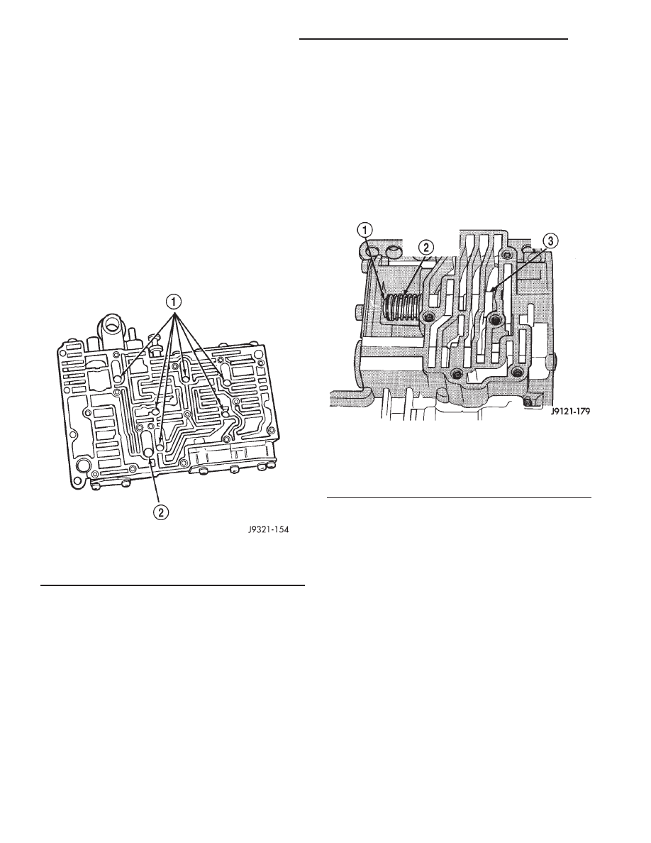
(1) Note location of check balls in valve body upper
housing (Fig. 310). Then remove the one large diam-
eter and the six smaller diameter check balls.
(2) Remove governor plug and shuttle valve covers
(Fig. 312).
(3) Remove E-clip that secures shuttle valve sec-
ondary spring on valve stem (Fig. 311).
(4) Remove throttle plug, primary spring, shuttle
valve, secondary spring, and spring guides (Fig. 312).
(5) Remove boost valve retainer, spring and valve
if not previously removed.
(6) Remove throttle plug and 1-2 and 2-3 governor
plugs (Fig. 299).
(7) Turn upper housing around and remove limit
valve and shift valve covers (Fig. 313).
(8) Remove limit valve housing. Then remove
retainer, spring, limit valve, and 2-3 throttle plug
from limit valve housing (Fig. 313).
(9) Remove 1-2 shift control valve and spring (Fig.
313).
(10) Remove 1-2 shift valve and spring (Fig. 313).
(11) Remove 2-3 shift valve and spring from valve
body (Fig. 313).
(12) Remove pressure plug cover (Fig. 313).
(13) Remove line pressure plug, sleeve, throttle
pressure plug and spring (Fig. 313).
Fig. 310 Check Ball Locations In Upper Housing
1 - SMALL DIAMETER CHECK BALLS (6)
2 - LARGE DIAMETER CHECK BALL (1)
Fig. 311 Shuttle Valve E-Clip And Secondary Spring
Location
1 - E-CLIP
2 - SECONDARY SPRING AND GUIDES
3 - SHUTTLE VALVE
21 - 240
AUTOMATIC TRANSMISSION - 42RE
AN
VALVE BODY (Continued)