Dodge Dakota (R1). Manual - part 647


  Index      Dodge     Dodge Dakota (R1) - service repair manual 2000 year


Search            


Content   ..  645  646  647  648   ..


Dodge Dakota (R1). Manual - part 647


REMOVAL

The valve body can be removed for service without

having to remove the transmission assembly.

The valve body can be disassembled for cleaning

and inspection of the individual components.

The only replaceable valve body components are:
• Manual lever.

• Manual lever washer, seal, E-clip, and shaft

seal.

• Manual lever detent ball.

• Throttle lever.

• Fluid filter.

• Pressure adjusting screw bracket.

• Governor pressure solenoid.

• Governor pressure sensor (includes transmission

temperature thermistor).

• Converter clutch/overdrive solenoid assembly

and harness .

• Governor housing gasket.

• Solenoid case connector O-rings.
(1) Shift transmission into NEUTRAL.
(2) Raise vehicle.
(3) Remove gearshift and throttle levers from shaft

of valve body manual lever.

(4) Disconnect wires at solenoid case connector

(Fig. 284).

(5) Remove the transmission range sensor.
(6) Position drain pan under transmission oil pan.
(7) Remove transmission oil pan and gasket.
(8) Remove fluid filter from valve body.
(9) Remove bolts attaching valve body to transmis-

sion case.

(10) Lower valve body enough to remove accumu-

lator piston and springs.

(11) Work manual lever shaft and electrical con-

nector out of transmission case.

(12) Lower valve body, rotate valve body away

from case, pull park rod out of sprag, and remove
valve body (Fig. 285).

Fig. 283 Boost Valve After Lock-up

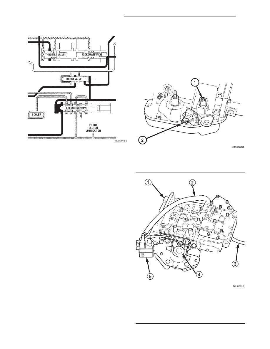
Fig. 284 Transmission Case Connector

1 - SOLENOID CASE CONNECTOR
2 - TRANSMISSION RANGE SENSOR

Fig. 285 Valve Body

1 - VALVE BODY
2 - WIRE HARNESS
3 - PARK ROD
4 - GOVERNOR PRESSURE SOLENOID
5 - GOVERNOR PRESSURE SENSOR

21 - 232

AUTOMATIC TRANSMISSION - 42RE

AN

VALVE BODY (Continued)

DISASSEMBLY

CAUTION: Do not clamp any valve body component
in a vise. This practice can damage the component
resulting in unsatisfactory operation after assembly
and installation. Do not use pliers to remove any of
the valves, plugs or springs and do not force any of
the components out or into place. The valves and
valve body housings will be damaged if force is
used. Tag or mark the valve body springs for refer-
ence as they are removed. Do not allow them to
become intermixed.

(1) Disconnect wires from governor pressure sen-

sor and solenoid.

(2) Remove screws attaching governor body and

retainer plate to transfer plate.

(3) Remove retainer plate, governor body and gas-

ket from transfer plate.

(4) Remove governor pressure sensor from gover-

nor body.

(5) Remove governor pressure solenoid by pulling

it straight out of bore in governor body. Remove and
discard solenoid O-rings if worn, cut, or torn.

(6) Remove small shoulder bolt that secures sole-

noid harness case connector to 3-4 accumulator hous-
ing (Fig. 286). Retain shoulder bolt. Either tape it to
harness or thread it back into accumulator housing
after connector removal.

(7) Unhook overdrive/converter solenoid harness

from 3-4 accumulator cover plate (Fig. 287).

(8) Turn valve body over and remove screws that

attach overdrive/converter solenoid assembly to valve
body (Fig. 288).

(9) Remove solenoid and harness assembly from

valve body (Fig. 289).

(10) Remove boost valve cover (Fig. 290).
(11) Remove boost valve retainer, valve spring and

boost valve (Fig. 291).

Fig. 286 Solenoid Harness Case Connector

Shoulder Bolt

1 - SOLENOID HARNESS CASE CONNECTOR
2 - 3-4 ACCUMULATOR HOUSING

Fig. 287 Unhooking Solenoid Harness From

Accumulator Cover Plate

1 - OVERDRIVE/CONVERTER SOLENOID WIRE HARNESS
2 - 3-4 ACCUMULATOR COVER PLATE

AN

AUTOMATIC TRANSMISSION - 42RE

21 - 233

VALVE BODY (Continued)

(12) Secure detent ball and spring with Retainer

Tool 6583 (Fig. 292).

(13) Remove park rod E-clip and separate rod from

manual lever (Fig. 293).

(14) Remove E-clip and washer that retains throt-

tle lever shaft in manual lever (Fig. 294).

(15) Remove manual lever and throttle lever (Fig.

295). Rotate and lift manual lever off valve body and
throttle lever shaft. Then slide throttle lever out of
valve body.

Fig. 288 Solenoid Assembly Screws

1 - OVERDRIVE/CONVERTER CLUTCH SOLENOID ASSEMBLY
2 - HARNESS

Fig. 289 Solenoid Assembly

1 - GOVERNOR SOLENOID WIRES
2 - CONVERTER CLUTCH SOLENOID
3 - SOLENOID SCREWS
4 - GOVERNOR SENSOR WIRES
5 - OVERDRIVE SOLENOID
6 - HARNESS
7 - CASE CONNECTOR

Fig. 290 Boost Valve

1 - BOOST VALVE HOUSING AND COVER
2 - BOOST VALVE TUBE

Fig. 291 Boost Valve Components

1 - SPRING AND VALVE RETAINER
2 - COVER SCREWS
3 - BOOST VALVE COVER
4 - BOOST VALVE PLUG
5 - BOOST VALVE
6 - BOOST VALVE SPRING

21 - 234

AUTOMATIC TRANSMISSION - 42RE

AN

VALVE BODY (Continued)

(16) Position pencil magnet next to detent housing

to catch detent ball and spring. Then carefully
remove Retainer Tool 6583 and remove detent ball
and spring (Fig. 296).

(17) Remove screws attaching pressure adjusting

screw bracket to valve body and transfer plate (Fig.
297). Hold bracket firmly against spring tension
while removing last screw.

Fig. 292 Detent Ball And Spring

1 - SPECIAL TOOL 6583 POSITIONED ON DETENT HOUSING

Fig. 293 Park Rod

1 - MANUAL LEVER
2 - E-CLIP
3 - PARK ROD

Fig. 294 Throttle Lever E-Clip And Washer

1 - THROTTLE LEVER SHAFT
2 - E-CLIP AND WASHER
3 - MANUAL SHAFT

Fig. 295 Manual And Throttle Lever

1 - PARK ROD
2 - MANUAL LEVER ASSEMBLY
3 - THROTTLE LEVER

AN

AUTOMATIC TRANSMISSION - 42RE

21 - 235

VALVE BODY (Continued)


Content   ..  645  646  647  648   ..