Dodge Dakota (R1). Manual - part 617


  Index      Dodge     Dodge Dakota (R1) - service repair manual 2000 year


Search            


Content   ..  615  616  617  618   ..


Dodge Dakota (R1). Manual - part 617


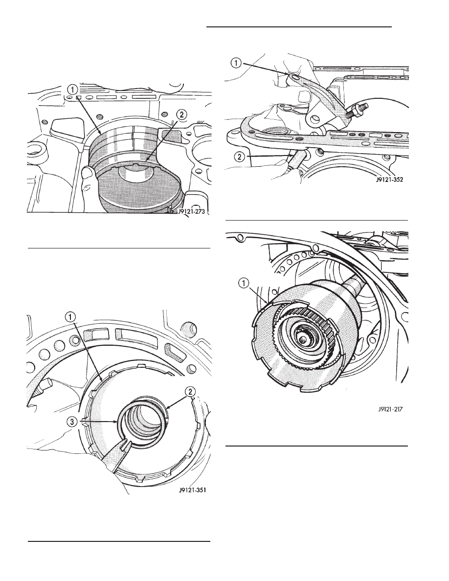
(e) Turn drum back and forth. Drum should rotate

freely in clockwise direction and lock in counter-
clockwise direction (as viewed from front of case).

(7) Install snap-ring that secures low-reverse drum

to hub of overdrive piston retainer (Fig. 38).

(8) Install rear band lever and pivot pin (Fig. 39).

Align lever with pin bores in case and push pivot pin
into place.

(9) Install planetary geartrain assembly (Fig. 40).

(10) Install thrust plate on intermediate shaft hub

(Fig. 41). Use petroleum jelly to hold thrust plate in
place.

(11) Check seal ring on rear clutch retainer hub

and seal rings on input shaft (Fig. 42). Also verify
that shaft seal rings are installed in sequence shown.

(12) Install rear clutch thrust washer (Fig. 43).

Use additional petroleum jelly to hold washer in
place if necessary.

Fig. 37 Installing Low-Reverse Drum

1 - REAR BAND
2 - LOW-REVERSE DRUM

Fig. 38 Installing Low-Reverse Drum Retaining

Snap-Ring

1 - LOW-REVERSE DRUM
2 - HUB OF OVERDRIVE PISTON RETAINER
3 - LOW-REVERSE DRUM SNAP-RING

Fig. 39 Rear Band Lever And Pivot Pin Installation

1 - REAR BAND LEVER
2 - LEVER PIVOT PIN

Fig. 40 Installing Planetary Geartrain

1 - PLANETARY GEARTRAIN AND INTERMEDIATE SHAFT
ASSEMBLY

21 - 112

AUTOMATIC TRANSMISSION - 42RE

AN

AUTOMATIC TRANSMISSION - 42RE (Continued)

(13) Align clutch discs in front clutch and install

front clutch on rear clutch (Fig. 44). Rotate front
clutch retainer back and forth until completely
seated on rear clutch retainer.

(14) Coat intermediate shaft thrust washer with

petroleum jelly. Then install washer in rear clutch
hub (Fig. 45). Use enough petroleum jelly to hold
washer in place. Be sure grooved side of washer faces
rearward (toward output shaft) as shown. Also note
that washer only fits one way in clutch hub. Note
thickness of this washer. It is a select fit part and is
used to control transmission end play.

(15) Align drive teeth on rear clutch discs with

small screwdriver (Fig. 46). This makes installation
on front planetary easier.

(16) Raise front end of transmission upward as far

as possible and support case with wood blocks. Front/
rear clutch and oil pump assemblies are easier to
install if transmission is as close to upright position
as possible.

(17) Slide front band into case.
(18) Install front and rear clutch units as assembly

(Fig. 47). Align rear clutch with front annulus gear
and install assembly in driving shell. Be sure output
shaft thrust washer and thrust plate are not dis-
placed during installation.

Fig. 41 Installing Intermediate Shaft Thrust Plate

1 - INTERMEDIATE SHAFT HUB
2 - INTERMEDIATE SHAFT THRUST PLATE

Fig. 42 Input Shaft Seal Ring Location

1 - INPUT SHAFT
2 - TEFLON SEAL RING
3 - PLASTIC SEAL RING
4 - REAR CLUTCH RETAINER

Fig. 43 Installing Rear Clutch Thrust Washer

1 - REAR CLUTCH RETAINER
2 - REAR CLUTCH THRUST WASHER (FIBER)

Fig. 44 Assembling Front And Rear Clutch Units

1 - TURN FRONT CLUTCH BACK & FORTH UNTIL SEATED
2 - REAR CLUTCH ASSEMBLY

AN

AUTOMATIC TRANSMISSION - 42RE

21 - 113

AUTOMATIC TRANSMISSION - 42RE (Continued)

(19) Carefully work assembled clutches back and

forth to engage and seat rear clutch discs on front
annulus gear. Also be sure front clutch drive lugs are
fully engaged in slots of driving shell after installation.

(20) Assemble front band strut.
(21) Install front band adjuster, strut and adjust-

ing screw (Fig. 48).

(22) Tighten band adjusting screw until band just

grips clutch retainer. Verify that front/rear clutches
are still seated before continuing.

Fig. 45 Installing Intermediate Shaft Thrust Plate

1 - INTERMEDIATE SHAFT THRUST WASHER
2 - INPUT SHAFT
3 - REAR CLUTCH RETAINER HUB

Fig. 46 Aligning Rear Clutch Disc Lugs

1 - REAR CLUTCH DISCS
2 - USE SMALL SCREWDRIVER TO ALIGN CLUTCH DISC
TEETH

Fig. 47 Installing Front/Rear Clutch Assemblies

1 - INPUT SHAFT
2 - FRONT CLUTCH
3 - REAR CLUTCH

Fig. 48 Front Band Linkage Installation

1 - BAND LEVER
2 - BAND STRUT
3 - FRONT BAND

21 - 114

AUTOMATIC TRANSMISSION - 42RE

AN

AUTOMATIC TRANSMISSION - 42RE (Continued)

(23) Check seal rings on reaction shaft support

hub. Verify that seal rings are hooked together and
that front clutch thrust washer is properly positioned
(Fig. 49). Use petroleum jelly to hold thrust washer
in place if necessary.

(24) Lubricate oil pump body seal with petroleum

jelly. Lubricate pump shaft seal lip with petroleum
jelly.

(25) Thread two Pilot Stud Tools C-3288-B into

bolt holes in oil pump bore flange (Fig. 50).

(26) Align and install oil pump gasket (Fig. 50).

(27) Install oil pump (Fig. 51). Align and position

pump on pilot studs. Slide pump down studs and
work it into front clutch hub and case by hand. Then
install 2 or 3 pump bolts to hold pump in place.

(28) Remove pilot stud tools and install remaining

oil pump bolts. Tighten bolts alternately in diagonal
pattern to 20 N·m (15 ft. lbs.).

(29) Measure input shaft end play (Fig. 52).

NOTE: If end play is incorrect, transmission is
incorrectly assembled, or the intermediate shaft
thrust washer is incorrect. The intermediate shaft
thrust washer is selective.

(a) Attach Adapter 8266-6 to Handle 8266-8.
(b) Attach

dial

indicator

C-3339

to

Handle

8266-8.

(c) Install the assembled tool onto the input

shaft of the transmission and tighten the retaining
screw on Adapter 8266-6 to secure it to the input
shaft.

(d) Position the dial indicator plunger against a

flat spot on the oil pump and zero the dial indica-
tor.

(e) Move input shaft in and out and record read-

ing. End play should be 0.56-2.31 mm (0.022-0.091
in.). Adjust as necessary.
(30) Install accumulator piston and inner and

outer springs (Fig. 53).

(31) Verify that valve body solenoid harness is

secured in 3-4 accumulator housing cover plate.

Fig. 49 Reaction Shaft Support Seal Rings And

Front Clutch Thrust Washer

1 - REACTION SHAFT SUPPORT HUB
2 - FRONT CLUTCH THRUST WASHER
3 - SEAL RINGS

Fig. 50 Installing Pilot Studs And Oil Pump Gasket

1 - OIL PUMP GASKET
2 - PILOT STUD TOOLS C-3288-B

Fig. 51 Installing Oil Pump

1 - OIL PUMP
2 - PILOT STUD TOOL
3 - PILOT STUD TOOL

AN

AUTOMATIC TRANSMISSION - 42RE

21 - 115

AUTOMATIC TRANSMISSION - 42RE (Continued)


Content   ..  615  616  617  618   ..