Dodge Dakota (R1). Manual - part 615


  Index      Dodge     Dodge Dakota (R1) - service repair manual 2000 year


Search            


Content   ..  613  614  615  616   ..


Dodge Dakota (R1). Manual - part 615


REMOVAL

The overdrive unit can be removed and serviced

separately. It is not necessary to remove the entire
transmission assembly to perform overdrive unit
repairs.

CAUTION: The transmission and torque converter
must be removed as an assembly to avoid compo-
nent damage. The converter driveplate, pump bush-
ing, or oil seal can be damaged if the converter is
left attached to the driveplate during removal. Be
sure to remove the transmission and converter as
an assembly.

(1) Disconnect battery negative cable.
(2) Hoist and support vehicle.
(3) Remove skid plate, if equipped.
(4) Remove skid plate support crossmember, if

equipped.

(5) Disconnect and lower or remove necessary

exhaust components.

(6) Mark

propeller

shaft

and

axle

companion

flanges for assembly alignment. Then disconnect and
remove propeller shaft. (Refer to 3 - DIFFERENTIAL
& DRIVELINE/PROPELLER SHAFT/PROPELLER
SHAFT - REMOVAL)

(7) Remove starter motor. (Refer to 8 - ELECTRI-

CAL/STARTING/STARTER MOTOR - REMOVAL)

(8) Support engine with suitable support stand

and wood block.

(9) Remove bolts attaching engine-to-transmission

brackets to transmission.

(10) Remove bolt and nut attaching each engine-

to-transmission bracket to the motor mounts.

(11) Remove bolts holding the engine-to-transmis-

sion brackets to the front axle, if equipped.

(12) Loosen bolts attaching engine-to-transmission

brackets to each side of the engine block.

(13) Raise engine slightly.
(14) Remove torque converter access cover.
(15) Tighten bolts attaching engine-to-transmis-

sion brackets to each side of the engine block.

(16) Lower engine.
(17) Disconnect fluid cooler lines at transmission.
(18) If transmission is being removed for overhaul,

remove transmission oil pan, drain fluid and reinstall
pan.

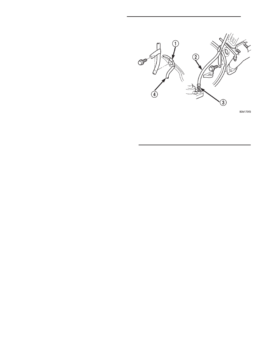
(19) Remove fill tube bracket bolts and pull tube

out of transmission. Retain fill tube seal. On 4x4
models, it will also be necessary to remove bolt
attaching transfer case vent tube to converter hous-
ing (Fig. 13).

(20) Rotate crankshaft in clockwise direction until

converter bolts are accessible. Then remove bolts one
at a time. Rotate crankshaft with socket wrench on
dampener bolt.

(21) Disconnect wires from the transmission range

sensor and transmission solenoids connector.

(22) Disconnect throttle valve cable from transmis-

sion bracket and throttle valve lever.

(23) On 4x4 models, disconnect shift rod from

transfer case shift lever. Or remove shift lever from
transfer case and tie rod and lever to chassis compo-
nent with wire.

(24) Raise transmission slightly with service jack

to relieve load on crossmember and supports.

(25) Remove bolts securing rear support and cush-

ion to transmission and crossmember. Raise trans-
mission slightly, slide exhaust hanger arm from
bracket (Fig. 14) and remove rear support.

(26) Remove bolts attaching crossmember to frame

and remove crossmember.

(27) On 4x4 models, disconnect vent hose from

transfer case. Then remove transfer case.

(28) Remove all converter housing bolts.
(29) Carefully work transmission and torque con-

verter assembly rearward off engine block dowels.

(30) Lower transmission and remove assembly

from under the vehicle.

DISASSEMBLY

(1) Clean transmission exterior with steam gun or

with solvent. Wear eye protection during cleaning
operations.

(2) Place transmission in a vertical position.
(3) Measure input shaft end play as follows (Fig.

15).

(a) Attach Adapter 8266-6 to Handle 8266-8.
(b) Attach

dial

indicator

C-3339

to

Handle

8266-8.

Fig. 13 Fill Tube Attachment

1 - TRANSFER CASE VENT TUBE
2 - FILL TUBE (V8)
3 - TUBE SEAL
4 - FILL TUBE (V6)

21 - 104

AUTOMATIC TRANSMISSION - 42RE

AN

AUTOMATIC TRANSMISSION - 42RE (Continued)

(c) Install the assembled tool onto the input

shaft of the transmission and tighten the retaining
screw on Adapter 8266-6 to secure it to the input
shaft.

(d) Position the dial indicator plunger against a

flat spot on the oil pump and zero the dial indica-
tor.

(e) Move the input shaft in and out. Record the

maximum travel for assembly reference.

(4) Remove shift and throttle levers from valve

body manual lever shaft.

(5) Place transmission in horizontal position.
(6) Remove transmission oil pan and gasket.
(7) Remove filter from valve body (Fig. 16). Keep

filter screws separate from other valve body screws.
Filter screws are longer and should be kept with fil-
ter.

(8) Remove the transmission range sensor.
(9) Remove hex head bolts attaching valve body to

transmission case (Fig. 17). A total of 10 bolts are
used. Note different bolt lengths for assembly refer-
ence.

(10) Remove valve body assembly. Push valve body

harness connector out of case. Then work park rod
and valve body out of case (Fig. 18).

(11) Remove accumulator piston and inner and

outer springs (Fig. 19).

(12) Remove pump oil seal with suitable pry tool

or slide-hammer mounted screw.

(13) Loosen front band adjusting screw locknut 4-5

turns. Then tighten band adjusting screw until band
is tight around front clutch retainer. This prevents
front/rear clutches from coming out with pump and
possibly damaging clutch or pump components.

(14) Remove oil pump bolts.
(15) Thread bolts of Slide Hammer Tools C-3752

into threaded holes in pump body flange (Fig. 20).

(16) Bump slide hammer weights outward to

remove pump and reaction shaft support assembly
from case (Fig. 20).

Fig. 14 Rear Support and Cushion

1 - EXHAUST PIPE ARM AND BRACKET
2 - CROSSMEMBER
3 - REAR SUPPORT AND CUSHION

Fig. 15 Checking Input Shaft End Play

1 - TOOL 8266-8
2 - TOOL 8266-6
3 - TOOL C-3339

Fig. 16 Oil Filter Removal

1 - OIL FILTER
2 - VALVE BODY
3 - FILTER SCREWS (2)

AN

AUTOMATIC TRANSMISSION - 42RE

21 - 105

AUTOMATIC TRANSMISSION - 42RE (Continued)

(17) Loosen front band adjusting screw until band

is completely loose.

(18) Squeeze front band together and remove band

strut (Fig. 21).

(19) Remove front band lever (Fig. 22).
(20) Remove front band lever shaft plug, if neces-

sary, from converter housing.

(21) Remove front band lever shaft.

Fig. 17 Valve Body Bolt Locations

1 - VALVE BODY BOLTS
2 - VALVE BODY BOLTS

Fig. 18 Valve Body Removal

1 - GOVERNOR PRESSURE SENSOR
2 - VALVE BODY
3 - PARK ROD
4 - ACCUMULATOR PISTON
5 - GOVERNOR PRESSURE SOLENOID

Fig. 19 Accumulator Piston And Springs

1 - ACCUMULATOR PISTON
2 - OUTER SPRING
3 - INNER SPRING

Fig. 20 Removing Oil Pump And Reaction Shaft

Support Assembly

1 - OIL PUMP AND REACTION SHAFT SUPPORT ASSEMBLY
2 - SLIDE HAMMER TOOLS C-3752

21 - 106

AUTOMATIC TRANSMISSION - 42RE

AN

AUTOMATIC TRANSMISSION - 42RE (Continued)

(22) Remove front and rear clutch units as assem-

bly. Grasp input shaft, hold clutch units together and
remove them from case (Fig. 23).

(23) Lift front clutch off rear clutch (Fig. 24). Set

clutch units aside for overhaul.

(24) Remove intermediate shaft thrust washer

from front end of shaft or from rear clutch hub (Fig.
25).

(25) Remove output shaft thrust plate from inter-

mediate shaft hub (Fig. 26).

Fig. 21 Removing Front Band Strut

1 - BAND LEVER
2 - BAND STRUT
3 - FRONT BAND

Fig. 22 Removing Front Band Lever

1 - FRONT BAND LEVER

Fig. 23 Removing Front/Rear Clutch Assemblies

1 - INPUT SHAFT
2 - FRONT CLUTCH
3 - REAR CLUTCH

Fig. 24 Separating Front/Rear Clutch Assemblies

1 - FRONT CLUTCH
2 - REAR CLUTCH

AN

AUTOMATIC TRANSMISSION - 42RE

21 - 107

AUTOMATIC TRANSMISSION - 42RE (Continued)


Content   ..  613  614  615  616   ..