Dodge Dakota (R1). Manual - part 616


  Index      Dodge     Dodge Dakota (R1) - service repair manual 2000 year


Search            


Content   ..  614  615  616  617   ..


Dodge Dakota (R1). Manual - part 616


(26) Slide front band off driving shell (Fig. 27) and

remove band from case.

(27) Remove planetary geartrain as assembly (Fig.

28). Support geartrain with both hands during
removal. Do not allow machined surfaces on interme-
diate shaft or overdrive piston retainer to become
nicked or scratched.

(28) If overdrive unit is not to be serviced, install

Alignment Shaft 6227-2 into the overdrive unit to
prevent misalignment of the overdrive clutches dur-
ing service of main transmission components.

(29) Loosen rear band adjusting screw 4-5 turns.
(30) Remove low-reverse drum snap-ring (Fig. 29).

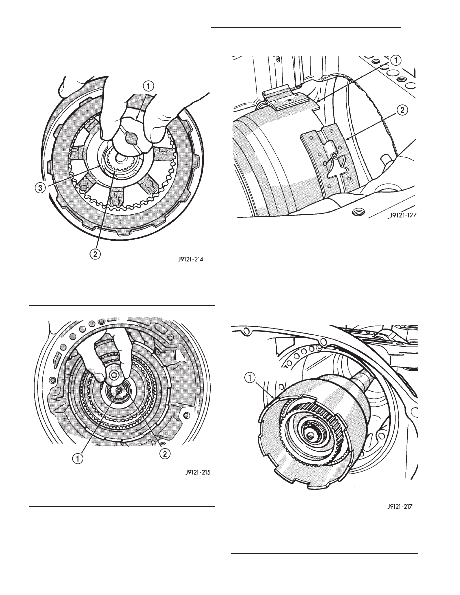
Fig. 25 Removing Intermediate Shaft Thrust Washer

1 - INTERMEDIATE SHAFT THRUST WASHER
2 - INPUT SHAFT
3 - REAR CLUTCH RETAINER HUB

Fig. 26 Removing Intermediate Shaft Thrust Plate

1 - INTERMEDIATE SHAFT HUB
2 - INTERMEDIATE SHAFT THRUST PLATE

Fig. 27 Front Band Removal

1 - DRIVING SHELL
2 - FRONT BAND

Fig. 28 Removing Planetary Geartrain And

Intermediate Shaft Assembly

1 - PLANETARY GEARTRAIN AND INTERMEDIATE SHAFT
ASSEMBLY

21 - 108

AUTOMATIC TRANSMISSION - 42RE

AN

AUTOMATIC TRANSMISSION - 42RE (Continued)

(31) Remove low-reverse drum and reverse band.
(32) Remove overrunning clutch roller and spring

assembly as a unit (Fig. 30).

(33) Compress front servo rod guide about 1/8 inch

with Valve Spring Compressor C-3422-B (Fig. 31).

(34) Remove front servo rod guide snap-ring. Exer-

cise caution when removing snap-ring. Servo bore
can be scratched or nicked if care is not exercised.

(35) Remove compressor tools and remove front

servo rod guide, spring and servo piston.

(36) Compress rear servo spring retainer about

1/16 inch with Valve Spring Compressor C-3422-B
(Fig. 32).

(37) Remove rear servo spring retainer snap-ring.

Then remove compressor tools and remove rear servo
spring and piston.

(38) Inspect transmission components.

NOTE: To Service the overrunning clutch cam or
overdrive piston retainer, refer to the Overrunning
Clutch Cam service procedure in this section.

CLEANING

Clean the case in a solvent tank. Flush the case

bores and fluid passages thoroughly with solvent.
Dry the case and all fluid passages with compressed
air. Be sure all solvent is removed from the case and
that all fluid passages are clear.

NOTE: Do not use shop towels or rags to dry the
case (or any other transmission component) unless
they are made from lint-free materials. Lint will stick
to case surfaces and transmission components and
circulate throughout the transmission after assem-
bly. A sufficient quantity of lint can block fluid pas-
sages and interfere with valve body operation.

Lubricate transmission parts with Mopar® ATF +4,

type 9602, transmission fluid during overhaul and
assembly. Use petroleum jelly, Mopar® Door Ease, or
Ru-Glyde™ to prelubricate seals, O-rings, and thrust

Fig. 29 Removing Low-Reverse Drum Snap-Ring

1 - LOW-REVERSE DRUM
2 - HUB OF OVERDRIVE PISTON RETAINER
3 - LOW-REVERSE DRUM SNAP-RING

Fig. 30 Overrunning Clutch Assembly Removal

1 - OVERRUNNING CLUTCH CAM
2 - REAR BAND REACTION PIN
3 - OVERRUNNING CLUTCH ASSEMBLY

Fig. 31 Compressing Front Servo Rod Guide

1 - SPRING COMPRESSOR TOOL C-3422-B
2 - ROD GUIDE SNAP-RING

AN

AUTOMATIC TRANSMISSION - 42RE

21 - 109

AUTOMATIC TRANSMISSION - 42RE (Continued)

washers. Petroleum jelly can also be used to hold
parts in place during reassembly.

INSPECTION

Inspect the case for cracks, porous spots, worn

bores, or damaged threads. Damaged threads can be
repaired with Helicoil thread inserts. However, the
case will have to be replaced if it exhibits any type of
damage or wear.

Lubricate the front band adjusting screw threads

with petroleum jelly and thread the screw part-way
into the case. Be sure the screw turns freely.

Inspect the transmission bushings during overhaul.

Bushing condition is important as worn, scored bush-
ings contribute to low pressures, clutch slip and
accelerated wear of other components. However, do
not replace bushings as a matter of course. Replace
bushings only when they are actually worn, or
scored.

Use recommended tools to replace bushings. The

tools are sized and designed to remove, install, and
seat bushings correctly. The bushing replacement
tools are included in Bushing Tool Set C-3887-B.

Pre-sized

service

bushings

are

available

for

replacement purposes. Only the sun gear bushings
are not serviced.

The use of crocus cloth is permissible where neces-

sary, providing it is used carefully. When used on
shafts, or valves, use extreme care to avoid rounding
off sharp edges. Sharp edges are vital as they pre-
vent foreign matter from getting between the valve
and valve bore.

Do not reuse oil seals, gaskets, seal rings, or

O-rings during overhaul. Replace these parts as a
matter of course. Also do not reuse snap rings or
E-clips that are bent or distorted. Replace these parts
as well.

ASSEMBLY

Do not allow dirt, grease, or foreign material to

enter the case or transmission components during
assembly. Keep the transmission case and compo-
nents clean. Also make sure the tools and workbench
area used for assembly operations are equally clean.

Shop towels used for wiping off tools and hands

must be made from lint free material. Lint will stick
to transmission parts and could interfere with valve
operation, or even restrict fluid passages.

Lubricate

the

transmission

components

with

Mopar® transmission fluid during reassembly. Use
Mopar® Door Ease, or Ru-Glyde™ on seals and
O-rings to ease installation.

Petroleum jelly can also be used to hold thrust

washers, thrust plates and gaskets in position during
assembly. However, do not use chassis grease, bear-
ing grease, white grease, or similar lubricants on any
transmission part. These types of lubricants can
eventually block or restrict fluid passages and inter-
fere with valve operation. Use petroleum jelly only.

Do not force parts into place. The transmission

components and subassemblies are easily installed by
hand when properly aligned.

If a part seems extremely difficult to install, it is

either misaligned or incorrectly assembled. Also ver-
ify that thrust washers, thrust plates and seal rings
are correctly positioned before assembly. These parts
can interfere with proper assembly if mis-positioned.

The planetary geartrain, front/rear clutch assem-

blies and oil pump are all much easier to install
when the transmission case is upright.

(1) Install rear servo piston, spring and retainer

(Fig. 33). Install spring on top of servo piston and
install retainer on top of spring.

(2) Install

front

servo

piston

assembly,

servo

spring and rod guide (Fig. 34).

(3) Compress front/rear servo springs with Valve

Spring Compressor C-3422-B and install each servo
snap-ring (Fig. 35).

Fig. 32 Compressing Rear Servo Spring

1 - FRONT SERVO SNAP-RING
2 - REAR SERVO SNAP-RING
3 - SPECIAL TOOL

21 - 110

AUTOMATIC TRANSMISSION - 42RE

AN

AUTOMATIC TRANSMISSION - 42RE (Continued)

(4) Lubricate clutch cam rollers with transmission

fluid.

(5) Install rear band in case (Fig. 36). Be sure twin

lugs on band are seated against reaction pin.

(6) Install low-reverse drum and check overrun-

ning clutch operation as follows:

(a) Lubricate overrunning clutch race (on drum

hub) with transmission fluid.

(b) Guide drum through rear band.

(c) Tilt drum slightly and start race (on drum

hub) into overrunning clutch rollers.

(d) Press drum rearward and turn it in clock-

wise direction until drum seats in overrunning
clutch (Fig. 37).

Fig. 33 Rear Servo Components

1 - SERVO PISTON
2 - PISTON SPRING
3 - SNAP-RING
4 - RETAINER
5 - PISTON SEAL

Fig. 34 Front Servo Components

1 - PISTON SEAL RINGS
2 - SERVO PISTON
3 - SNAP-RING
4 - ROD GUIDE
5 - SPRING
6 - ROD

Fig. 35 Compressing Front/Rear Servo Springs

1 - SPRING COMPRESSOR TOOL C-3422-B
2 - ROD GUIDE SNAP-RING

Fig. 36 Rear Band Installation

1 - REAR BAND

AN

AUTOMATIC TRANSMISSION - 42RE

21 - 111

AUTOMATIC TRANSMISSION - 42RE (Continued)


Content   ..  614  615  616  617   ..