Dodge Dakota (R1). Manual - part 594


  Index      Dodge     Dodge Dakota (R1) - service repair manual 2000 year


Search            


Content   ..  592  593  594  595   ..


Dodge Dakota (R1). Manual - part 594


NOTE: The synchro hub is a press fit design. There
may be instances where the press is not necessary.
As long as there is a snug fit between the hub and
the shaft, the hub does not need to be replaced.

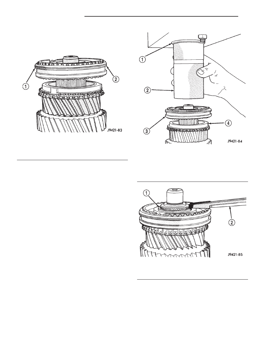
(29) Press 3-4 synchro assembly onto output shaft

with shop press and suitable size pipe tool (Fig. 59).
Press tool must be as close to the hub center as pos-
sible but not contacting the shaft splines.

(30) Install 3-4 synchro hub new snap ring (Fig.

60) with thickest snap ring that will fit in shaft
groove. Verify snap ring is seated in groove.

(31) Verify position of synchro sleeves before pro-

ceeding (Fig. 61).

Fig. 58 START 3-4 SYNCHRO HUB ON OUTPUT

SHAFT

1 - GROOVED SIDE OF SLEEVE (TO FRONT)
2 - 3-4 SYNCHRO ASSEMBLY

Fig. 59 PRESS 3-4 SYNCHRO ASSEMBLY ON

SHAFT

1 - PRESS RAM
2 - PIPE TOOL
3 - 3-4 SYNCHRO
4 - THIRD SPEED SYNCHRO RING

Fig. 60 3-4 SYNCHRO HUB SNAP RING

1 - 3-4 SYNCHRO HUB SNAP RING
2 - HEAVY DUTY SNAP RING PLIERS

21 - 20

MANUAL - NV1500

AN

MANUAL - NV1500 (Continued)

GEARTRAIN

(1) Install input shaft into Support Stand 8355

(Fig. 62).

(2) Install pilot bearing in input shaft (Fig. 62).
(3) Install fourth gear synchro ring on input shaft

(Fig. 63).

(4) Install assembled output shaft and geartrain in

input shaft (Fig. 64). Rotate output shaft until the
3-4 synchro ring seats in synchro hub and sleeve.

(5) Slide countershaft into fixture slot. Verify coun-

tershaft and output shaft gears are fully meshed
with the mainshaft gears (Fig. 65).

(6) Thread one Pilot Stud 8120 in center or pas-

senger side hole of output shaft bearing retainer.
Then position retainer on fifth gear.

(7) Assemble 1-2 and fifth reverse-shift forks (Fig.

66). Arm of fifth-reverse fork goes through slot in 1-2
fork.

Fig. 61 SYNCHRO SLEEVE POSITION

1 - 2 GROOVES
2 - 1 GROOVE
3 - 2 GROOVES
4 - FOURTH GEAR
5 - THIRD GEAR

6 - SECOND GEAR
7 - FIRST GEAR
8 - REVERSE GEAR
9 - FIFTH GEAR

Fig. 62 INPUT SHAFT AND PILOT BEARING

1 - PILOT BEARING
2 - INPUT SHAFT
3 - STAND 8355

AN

MANUAL - NV1500

21 - 21

MANUAL - NV1500 (Continued)

(8) Install assembled shift forks in synchro sleeves

(Fig. 67). Verify forks are seated in sleeves.

Fig. 63 FOURTH GEAR SYNCHRO RING ON INPUT

SHAFT

1 - FOURTH GEAR SYNCHRO RING
2 - INPUT SHAFT
3 - STAND 8355

Fig. 64 MAINSHAFT ON SUPPORT STAND

1 - MAIN SHAFT
2 - SUPPORT STAND 8355

Fig. 65 COUNTERSHAFT ON SUPPORT STAND

1 - COUNTER SHAFT
2 - MAIN SHAFT
3 - SUPPORT STAND 8355

Fig. 66 1-2 AND FIFTH-REVERSE SHIFT FORKS

1 - INSERT ARM THROUGH 1-2 FORK
2 - 1-2 FORK
3 - FIFTH-REVERSE FORK

21 - 22

MANUAL - NV1500

AN

MANUAL - NV1500 (Continued)

REAR HOUSING

(1) Lubricate countershaft rear bearing race.
(2) Install rear housing onto geartrain (Fig. 68).

Verify bearing retainer pilot stud is in correct bolt
hole and countershaft and output shaft bearings are
aligned in housing and on countershaft.

(3) Seat rear housing on output shaft rear bearing

and countershaft. Tap housing into place with plastic
or rawhide hammer.

(4) Apply Mopar® Gasket Maker or equivalent to

bolt threads, bolt shanks and under bolt heads (Fig.
69).

(5) Start first two bolts in retainer (Fig. 70). It

may be necessary to move retainer rearward (with
pilot stud) in order to start bolts.

(6) Remove

Pilot

Stud

8120

and

install

last

retainer bolt (Fig. 70).

(7) Tighten all three retainer bolts to 22 N·m (16

ft. lbs.).

NOTE: All bolts except the reverse idler shaft bolts
have o-rings to seal the bolts to the transmission
case. Inspect the o-rings to ensure that they are in
good condition.

REVERSE IDLER

(1) Remove geartrain and housing assembly from

support stand with aid of helper.

(2) Assemble shaft, gear and washer (without

bearing or support) and install into housing (Fig. 71).

Fig. 67 SHIFT FORKS AND SYNCHROS

1 - FIFTH REVERSE SHIFT FORK
2 - 1-2 SHIFT FORK

Fig. 68 REAR HOUSING

1 - REAR HOUSING
2 - SHIFT FORKS AND GEARTRAIN

Fig. 69 RETAINER AND HOUSING BOLTS

1 - MOPAR GASKET MAKER
2 - RETAINER AND HOUSING BOLTS
3 - APPLY SEALER TO UNDERSIDE OF BOLT HEAD, SHANK
AND THREADS

AN

MANUAL - NV1500

21 - 23

MANUAL - NV1500 (Continued)


Content   ..  592  593  594  595   ..