Dodge Dakota (R1). Manual - part 592


  Index      Dodge     Dodge Dakota (R1) - service repair manual 2000 year


Search            


Content   ..  590  591  592  593   ..


Dodge Dakota (R1). Manual - part 592


can be smoothed off with 320/400 grit emery cloth
followed by polishing with crocus cloth. Replace the
shift shaft bushing or bearing if damaged.

Replace the shaft lever and bushing if either part

is deformed, or worn. Do not attempt to salvage these
parts as shift fork binding will occur. Replace the roll
pin that secures the lever to the shaft.

FRONT/REAR HOUSINGS AND BEARING
RETAINERS

Clean the gears, shafts, shift components and

transmission housings with a standard parts clean-
ing solvent. Do not use acid or corrosive base sol-
vents. Dry all parts except bearings with compressed
air.

Clean the shaft bearings with a mild solvent such

as Mopar® degreasing solvent, Gunk or similar sol-
vents. Do not dry the bearings with compressed air.
Allow the bearings to either air dry or wipe them dry
with clean shop towels.

Inspect the housings carefully. Look for cracks,

stripped threads, scored mating surfaces, damaged
bearing bores or worn dowel pin holes. Minor nicks
on mating surfaces can be dressed off with a fine file
or emery cloth. Damaged threads can be renewed by
either re-tapping or installing Helicoil inserts.

NOTE: The front housing contains the countershaft
front bearing race. The rear housing contains the
countershaft rear bearing race. If a countershaft
bearing failure results, the bearing races must be
replaced also.

Inspect input shaft bearing retainer. Be sure the

release bearing slide surface of the retainer is in
good condition. Minor nicks on the surface can be
smoothed off with 320/420 grit emery cloth and final
polished with oil coated crocus cloth. Replace the
retainer seal if necessary.

Inspect output shaft bearing retainer. Be sure the

U-shaped retainer is flat and free of distortion.
Replace the retainer if the threads are damaged or if
the retainer is bent or cracked.

COUNTERSHAFT BEARINGS AND RACES

The countershaft bearings are standard tapered

roller bearings with matching races. The races are
pressed into the front and rear housings. Inspect
countershaft bearings and races for abnormal wear
or damage.

REVERSE IDLER COMPONENTS

Inspect idler gear, bearing, shaft, thrust washer

and support for excessive wear or failure (Fig. 34).
Replace bearing if any of the needle bearing rollers

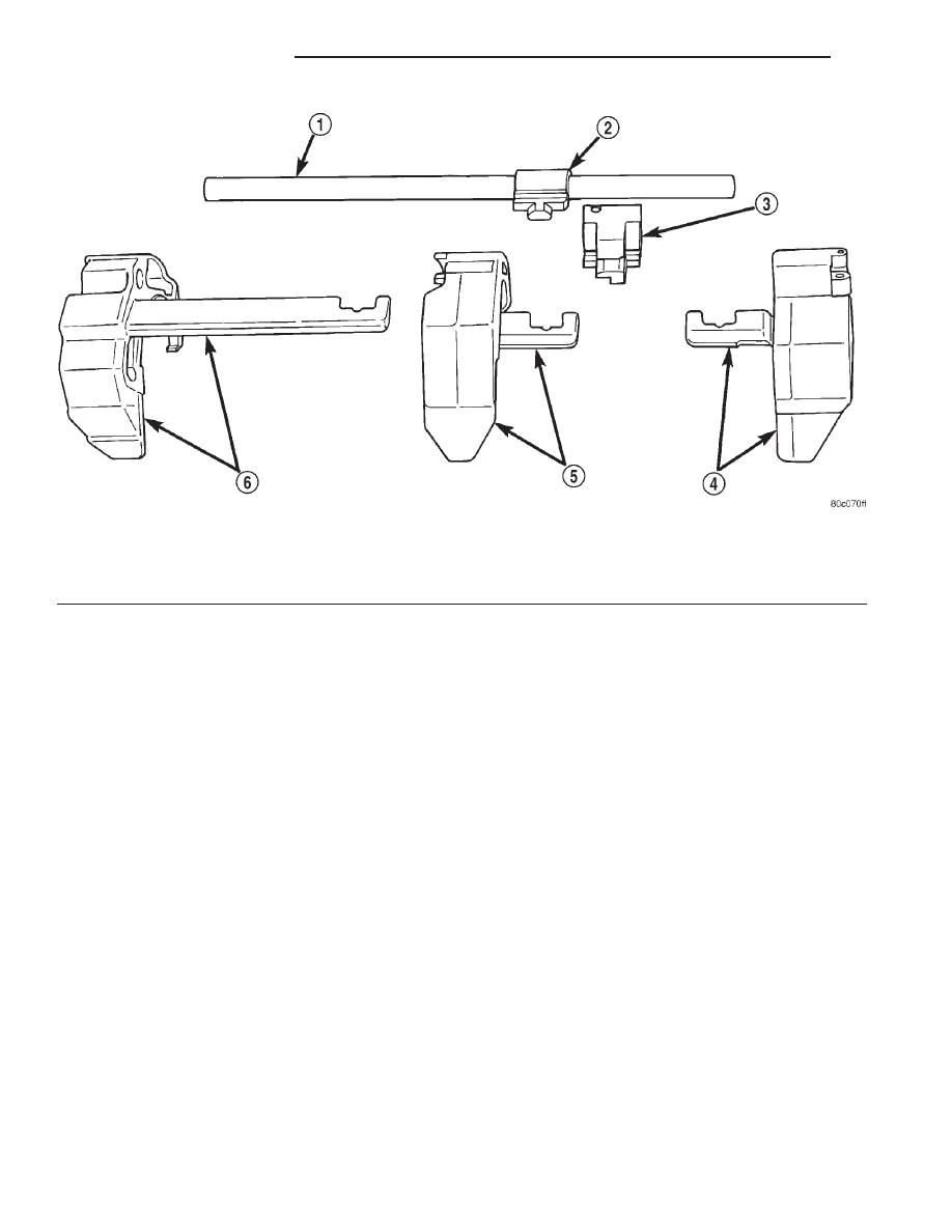
Fig. 33 SHIFT FORKS AND SHAFT

1 - SHIFT SHAFT
2 - SHAFT LEVER
3 - SHAFT LEVER BUSHING

4 - 3-4 SHIFT FORK
5 - 1-2 SHIFT FORK
6 - FIFTH-REVERSE SHIFT FORK

21 - 12

MANUAL - NV1500

AN

MANUAL - NV1500 (Continued)

are worn, chipped, cracked, flat-spotted or brinnelled.
Also replace the bearing if the plastic bearing cage is
damaged or distorted.

Replace thrust washer, if cracked, chipped or worn.

Replace idler gear if the teeth are chipped, cracked or
worn thin. Replace shaft if worn, scored or the bolt
threads are damaged beyond repair. Replace support
segment if cracked or chipped and replace the idler
attaching bolts if the threads are damaged.

Shift Socket

Inspect shift socket for wear or damage. Replace

socket if the roll pin or shift shaft bores are dam-
aged. Minor nicks in the shift lever ball seat in the
socket can be smoothed down with 400 grit emery or
wet/dry paper. Replace socket if the ball seat is worn,
or cracked. Do not reuse the original shift socket roll
pin. The socket roll pin is approximately is approxi-
mately 33 mm (1-1/4 in.) long.

Output Shaft And Geartrain

Inspect all gears for worn, cracked, chipped or bro-

ken teeth. Check condition of the bearing bore in each
gear. The bores should be smooth and free of surface
damage. Discoloration of the gear bores is a normal
occurrence and is not a reason for replacement.
Replace gears only when tooth damage has occurred or
if the bores are brinnelled or severely scored.

Inspect shaft splines and bearings surfaces. Minor

nicks on the bearing surfaces can be smoothed with
320/420 grit emery and final polished with crocus
cloth. Replace the shaft if the splines are damaged or
bearing surfaces are deeply scored, worn or brinnelled.

ASSEMBLY

SYNCHRONIZER

NOTE: The easiest method of assembling each syn-
chro is to install the springs, struts and detent balls
one at a time.

(1) Slide the sleeve part way onto the hub. Leave

enough room to install the spring in the hub and the
strut in the hub groove.

(2) Install first spring in the hub and then install

a strut over the spring. Verify spring is seated in the
spring bore in the strut.

(3) Slide the sleeve onto the hub just far enough to

hold the first strut and spring in place.

(4) Place detent ball in the top of the strut. Then

work the sleeve over the ball to hold it in place. Use
a small flat blade screwdriver to press the ball into
place while moving the sleeve over it.

(5) Repeat procedure for the remaining springs,

struts and balls. Tape or rubber band each strut and
ball temporarily as they are installed.

(6) Verify the three springs, struts and detent balls

are all in place (Fig. 35).

Fig. 34 REVERSE IDLER ASSEMBLY

1 - SUPPORT
2 - BEARING
3 - WASHER
4 - GEAR
5 - SHAFT

Fig. 35 ASSEMBLED SYNCHRO COMPONENTS

1 - SLEEVE
2 - HUB SHOULDER
3 - SPRING (3)
4 - STRUT (3)
5 - DETENT BALL (3)
6 - HUB

AN

MANUAL - NV1500

21 - 13

MANUAL - NV1500 (Continued)

OUTPUT SHAFT

NOTE: Lubricate shaft, gears and bearings with rec-
ommended lubricant and immerse each synchro
ring in lubricant before installation. Petroleum jelly
can be used to hold parts in place.

(1) Install reverse gear needle bearing on shaft

(Fig. 36). Slide bearing up against shoulder on output
shaft.

(2) Install reverse gear over needle bearing (Fig.

37).

(3) Install solid brass synchro ring on reverse gear

(Fig. 38).

NOTE: This synchro ring is different than all the
rest. The angle on the friction face is 9° versus the
6.5° of all the other synchro rings.

(4) Start fifth-reverse synchro assembly on output

shaft splines by hand. Then seat synchro onto shaft
with shop press and Remover 6310-1 (Fig. 39).

CAUTION: Fifth-reverse synchro hub and sleeve
can be installed backwards. One side of the sleeve
has double grooves and offset teeth. This side must
be installed away from reverse gear (towards 5th).

NOTE: The synchro hub is a press fit design. There
may be instances where the press is not necessary.
As long as there is a snug fit between the hub and
the shaft, the hub does not need to be replaced.

Fig. 36 REVERSE GEAR BEARING

1 - REVERSE GEAR BEARING
2 - SHOULDER

Fig. 37 REVERSE GEAR

1 - REVERSE GEAR

Fig. 38 REVERSE GEAR SYNCHRO RING

1 - REVERSE GEAR
2 - SYNCHRO RING (SOLID BRASS)

Fig. 39 FIFTH-REVERSE SYNCHRO ASSEMBLY

1 - SPACER
2 - PRESS RAM
3 - REVERSE GEAR
4 - FIFTH-REVERSE SYNCHRO ASSEMBLY
5 - SPECIAL TOOL 6310-1
6 - PRESS BLOCKS
7 - OUTPUT SHAFT

21 - 14

MANUAL - NV1500

AN

MANUAL - NV1500 (Continued)

(5) Install new fifth-reverse hub snap ring (Fig.

40) and verify snap ring is seated in the shaft groove.

NOTE: Install thickest snap ring that will fit in shaft
groove.

(6) Install fifth gear synchro ring in synchro hub

and sleeve (Fig. 41).

(7) Install fifth gear bearing, spreading bearing

only enough to clear shoulder on output shaft (Fig.
42). Verify bearing is seated.

(8) Install fifth gear on shaft and onto bearing

(Fig. 43).

(9) Install output shaft bearing.
(10) Install output shaft bearing snap ring, spread

snap ring only enough to install it (Fig. 44). Verify
snap ring is seated in shaft groove.

Fig. 40 FIFTH-REVERSE SYNCHRO HUB SNAP

RING

1 - FIFTH-REVERSE SYNCHRO ASSEMBLY
2 - SNAP RING
3 - PRESS BED
4 - PRESS BLOCKS

Fig. 41 FIFTH GEAR SYNCHRO RING

1 - FIFTH-SPEED SYNCHRO RING
2 - FIFTH-REVERSE SYNCHRO ASSEMBLY

Fig. 42 FIFTH GEAR BEARING

1 - SHAFT SHOULDER
2 - FIFTH GEAR BEARING

Fig. 43 FIFTH GEAR

1 - FIFTH GEAR
2 - BEARING

AN

MANUAL - NV1500

21 - 15

MANUAL - NV1500 (Continued)


Content   ..  590  591  592  593   ..