Dodge Dakota (R1). Manual - part 587


  Index      Dodge     Dodge Dakota (R1) - service repair manual 2000 year


Search            


Content   ..  585  586  587  588   ..


Dodge Dakota (R1). Manual - part 587


(9) Install preload adjuster nut. Do not tighten

nut until after Over-Center Rotation Torque
adjustment has been made.

(10) Install gasket to side cover and bend tabs

around edges of side cover (Fig. 4).

(11) Install pitman shaft assembly and side cover

to housing.

(12) Install side cover bolts and tighten to 60 N·m

(44 ft. lbs.).

(13) Perform over-center rotation torque adjust-

ment.

CENTER LINK

REMOVAL

(1) Remove the outer and inner tie rod ends from

the center link.

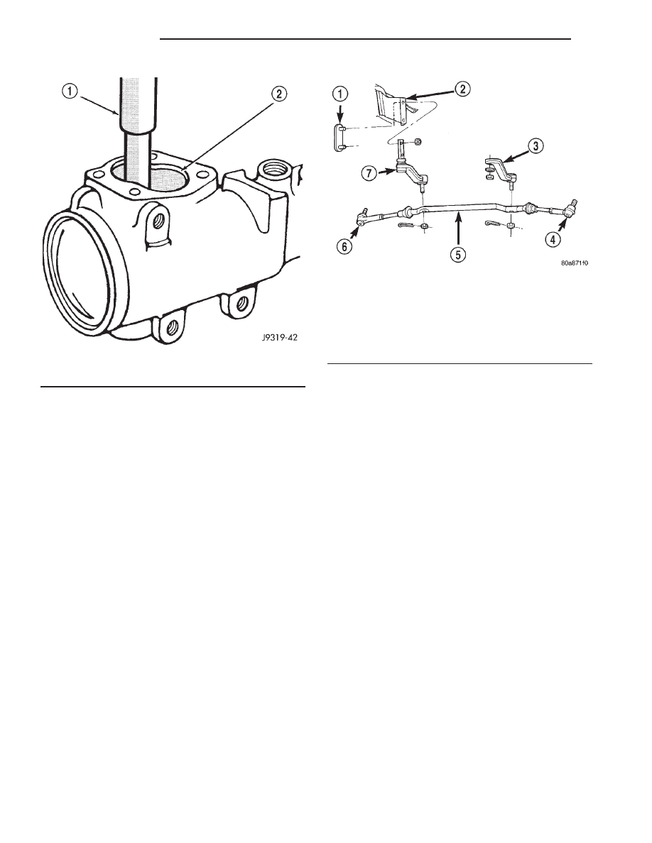
(2) Remove cotter pins and nuts from the idler

arm and pitman arm (Fig. 28).

(3) Separate the idler arm and pitman arm from

the center link with Puller C-3894-A.

(4) Remove center link.

INSTALLATION

(1) Install the center link on the pitman arm and

idler arm (Fig. 28).

(2) Tighten the pitman arm nut to 88 N·m (65 ft.

lbs.). Install new cotter pin.

(3) Tighten the idler arm nut to 88 N·m (65 ft.

lbs.). Install new cotter pin.

(4) Install the inner and outer tie rod ends on the

center link.

(5) Set toe pattern,(Refer to 2 - SUSPENSION/

WHEEL ALIGNMENT - STANDARD PROCEDURE).

IDLER ARM

REMOVAL

(1) Remove the cotter pin and nut from the idler

arm at the center link.

(2) Separate idler arm from the center link with

Puller C-3894-A.

(3) Remove nuts from the stud plate and remove

idler arm (Fig. 28).

INSTALLATION

(1) Position the idler arm on the stud plate and

tighten the nuts to 149 N·m (110 ft. lbs.).

(2) Install idler arm to the center link and tighten

nut to 88 N·m (65 ft. lbs.) (Fig. 28). Install a new cot-
ter pin.

(3) Set toe pattern,(Refer to 2 - SUSPENSION/

WHEEL ALIGNMENT - STANDARD PROCEDURE).

PITMAN ARM

REMOVAL

To remove the pitman arm the steering gear must

be removed from the vehicle. Refer to steering gear
removal for the procedure.

Fig. 27 Needle Bearing Removal

1 - REMOVER
2 - SIDE COVER AREA

Fig. 28 Steering Linkage

1 - STUD PLATE
2 - FRAME BRACKET
3 - PITMAN ARM
4 - THE ROD END
5 - CENTER LINK
6 - TIE ROD END
7 - IDLER ARM

19a - 10

STEERING

R1

PITMAN SHAFT SEAL (Continued)

PUMP

TABLE OF CONTENTS

page

page

PUMP

REMOVAL . . . . . . . . . . . . . . . . . . . . . . . . . . . . . . 11
INSTALLATION. . . . . . . . . . . . . . . . . . . . . . . . . . . 13

HOSES

REMOVAL . . . . . . . . . . . . . . . . . . . . . . . . . . . . . . 15

INSTALLATION. . . . . . . . . . . . . . . . . . . . . . . . . . . 16

RESERVOIR

REMOVAL . . . . . . . . . . . . . . . . . . . . . . . . . . . . . . 17
INSTALLATION. . . . . . . . . . . . . . . . . . . . . . . . . . . 17

PUMP

REMOVAL – POWER STEERING PUMP – 2.5L
DIESEL

(1) Disconnect and isolate the negative battery

cable.

(2) Remove the (2) refrigerant line support bracket

bolts from the generator mounting bracket and the
water manifold. This will allow the refrigerant lines and
the compressor assembly to be positioned out of the way
without having to recover the refrigerant system.

(3) Siphon as much power steering fluid as possi-

ble from the fluid reservoir (Fig. 1).

(4) Remove the accessory drive belt from the vehi-

cle (Fig. 2), (Refer to 7 - COOLING/ACCESSORY
DRIVE/DRIVE BELTS - REMOVAL) .

(5) Remove the power steering pump pulley. Use a

hex socket to secure the pump shaft while removing
the pulley retaining nut with a box wrench.

Fig. 1 Power Steering System

1 - PRESSURE HOSE
2 - POWER STEERING FLUID SUPPLY HOSE
3 - RETURN HOSES
4 - POWER STEERING FLUID COOLER

Fig. 2 Installing Accessory Drive Belt

1 - 1/2 DRIVE BREAKER BAR OR RATCHET
2 - UPPER RADIATOR HOSE
3 - FAN SHROUD

R1

PUMP

19a - 11

(6) Remove the power steering fluid pressure hose

from the pump (Fig. 1).

(7) Remove the upper left (as viewed from the left

side of the engine) engine mount bracket retaining
bolt from the engine block (Fig. 3).

(8) Install the engine bridge fixture (Fig. 4). Sup-

port the engine assembly.

(9) Raise the vehicle on the hoist.

NOTE: Mark the position of the H-Block (Fig. 5) in
relation to the compressor so it may be installed in
the same position.

(10) Disconnect the A/C compressor electrical con-

nector (Fig. 5).

(11) Loosen the H-Block intermediate shaft coupler

pinch bolt (Fig. 6).

(12) Remove

the

(2)

H–Block

retaining

bolts

threading into the compressor drive cup (Fig. 6).

(13) Support the compressor with mechanics wire

before proceeding to the next step.

(14) Remove the (4) compressor mounting bolts

(Fig. 5) and position the compressor assembly aside.

CAUTION: DO NOT LET THE COMPRESSOR HANG
FROM THE REFRIGERANT LINES. DAMAGE TO THE
REFRIGERANT LINES WILL OCCUR.

(15) Remove the H-Block intermediate shaft cou-

pler.

(16) Remove the power steering fluid supply hose

from the pump (Fig. 1).

(17) Remove the (2) left engine mount insulator

retaining nuts (Fig. 7).

Fig. 3 Power Steering Pump

1 - ENGINE MOUNT RETAINING NUTS
2 - POWER STEERING PUMP RETAINING NUTS
3 - ENGINE MOUNT BRACKET RETAINING BOLTS
4 - POWER STEERING PUMP

Fig. 4 Engine Bridge Fixture

1 - ENGINE BRIDGE FIXTURE

Fig. 5 Compressor Position & Orientation

1 - COMPRESSOR ELECTRICAL CONNECTOR
2 - REFRIGERANT LINE RETAINING BOLTS
3 - COMPRESSOR RETAINING BOLTS
4 - H-BLOCK

19a - 12

PUMP

R1

PUMP (Continued)

(18) Remove the remaining (3) engine mount

bracket retaining bolts from the engine block (Fig. 3).

Remove the engine mount and bracket from the vehi-
cle.

(19) Remove the (2) power steering pump retaining

nuts (Fig. 7). Remove the pump from the vehicle.

INSTALLATION – POWER STEERING PUMP -
2.5L DIESEL

CAUTION: Power steering system fluid may be con-
taminated

with

metal

shavings,

overheated

or

improper fluid. All fluid should be drained from the
system. After any component replacement, system
should be flushed and filled with Mopar Power
Steering fluid, or equivalent.

(1) Install the power steering pump. Torque the

retaining nuts to 27 N·m (20 ft. lbs.) (Fig. 8).

(2) Install the engine mount and the engine mount

bracket in the vehicle. Torque the engine mount
bracket retaining bolts to 61 N·m (45 ft. lbs.) (Fig. 8).

(3) Install the (2) left engine mount insulator

retaining nuts (Fig. 8). Torque the insulator nuts to
65 N·m (48 ft. lbs.).

(4) Install the power steering fluid supply hose on

the pump.

(5) Install the H-Block intermediate shaft coupler.

Fig. 6 Compressor Drive Assembly

1 - COMPRESSOR DRIVE CUP RETAINING BOLTS
(COMPRESSOR REMOVED)
2 - H-BLOCK ASSEMBLY
3 - INTERMEDIATE SHAFT COUPLER PINCH BOLT

Fig. 7 Power Steering Pump

1 - ENGINE MOUNT RETAINING NUTS
2 - POWER STEERING PUMP RETAINING NUTS
3 - ENGINE MOUNT BRACKET RETAINING BOLTS
4 - POWER STEERING PUMP

Fig. 8 Power Steering Pump

1 - ENGINE MOUNT RETAINING NUTS
2 - POWER STEERING PUMP RETAINING NUTS
3 - ENGINE MOUNT BRACKET RETAINING BOLTS
4 - POWER STEERING PUMP

R1

PUMP

19a - 13

PUMP (Continued)


Content   ..  585  586  587  588   ..