Dodge Dakota (R1). Manual - part 586


  Index      Dodge     Dodge Dakota (R1) - service repair manual 2000 year


Search            


Content   ..  584  585  586  587   ..


Dodge Dakota (R1). Manual - part 586


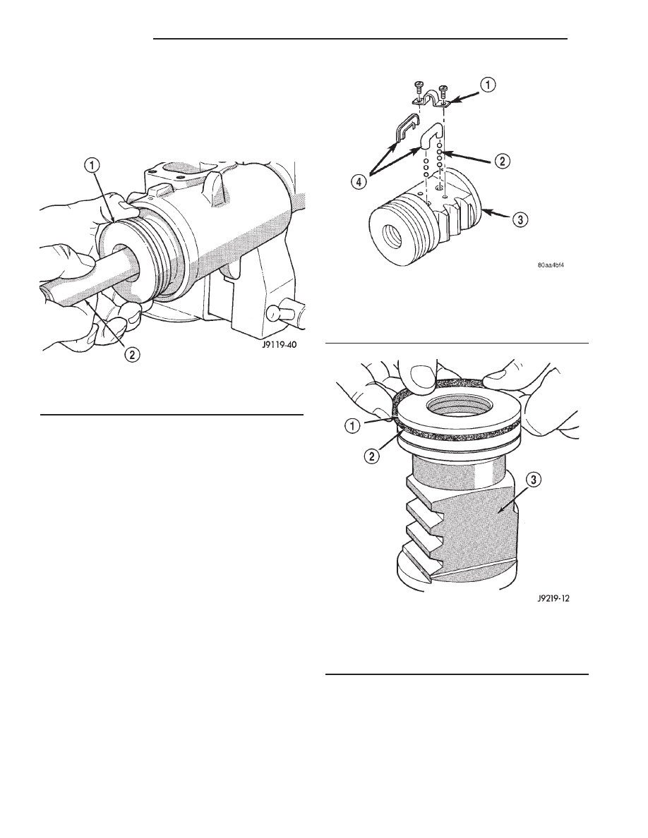
(5) Insert Arbor C-4175 into bore of rack piston

(Fig. 16) and hold tool tightly against worm shaft.

(6) Turn the stub shaft with a 12 point socket

COUNTERCLOCKWISE, this will force the rack pis-
ton onto the tool and hold the rack piston balls in
place.

(7) Remove the rack piston and tool together from

housing.

(8) Remove tool from rack piston.
(9) Remove rack piston balls.
(10) Remove clamp bolts, clamp and ball guide

(Fig. 17).

(11) Remove teflon ring and O-ring from the rack

piston (Fig. 18).

(12) Remove the adjuster lock nut and adjuster

nut from the stub shaft.

(13) Pull the stub shaft with the spool valve and

thrust support assembly out of the housing.

(14) Remove the worm shaft from the housing

(Fig. 19).

INSTALLATION

NOTE: Clean and dry all components and lubricate
with power steering fluid.

(1) Check for scores, nicks or burrs on the rack

piston finished surface. Slight wear is normal on the
worm gear surfaces.

(2) Install O-ring and teflon ring on the rack pis-

ton.

(3) Install worm shaft in the rack piston and align

worm shaft spiral groove with rack piston ball guide
hole (Fig. 20).

CAUTION: The rack piston balls must be installed
alternately into the rack piston and ball guide. This
maintains worm shaft preload. There are 12 black
balls and 12 silver (Chrome) balls. The black balls
are smaller than the silver balls.

Fig. 16 Rack Piston with Arbor

1 - RACK PISTON
2 - SPECIAL TOOL C-4175

Fig. 17 Rack Piston

1 - CLAMP
2 - BALLS
3 - RACK PISTON
4 - BALL GUIDE

Fig. 18 Rack Piston Teflon Ring and O-Ring

1 - TEFLON SEAL
2 - BACK-UP O-RING MUST BE INSTALLED UNDER PISTON
RING
3 - RACK PISTON NUT

19a - 6

STEERING

R1

WORM SHAFT (Continued)

(4) Lubricate and install rack piston balls through

return guide hole while turning worm shaft COUN-
TERCLOCKWISE (Fig. 20).

(5) Install remaining balls in guide using grease to

hold the balls in place (Fig. 21).

(6) Install the guide onto rack piston and install

clamp and clamp bolts. Tighten bolts to 58 N·m (43
ft. lbs.).

(7) Insert Arbor C-4175 into bore of rack piston

and hold tool tightly against worm shaft.

(8) Turn the worm shaft COUNTERCLOCKWISE

while pushing on the arbor. This will force the rack
piston onto the arbor and hold the rack piston balls
in place.

(9) Install the races and thrust bearing on the

worm shaft and install shaft in the housing (Fig. 19).

(10) Install the stub shaft with spool valve, thrust

support assembly and adjuster nut in the housing.

(11) Install the rack piston and arbor tool into the

housing.

(12) Hold arbor tightly against worm shaft and

turn stub shaft CLOCKWISE until rack piston is
seated on worm shaft.

(13) Install pitman shaft and side cover in the

housing.

(14) Install rack piston plug and tighten to 150

N·m (111 ft. lbs.).

(15) Install housing end plug.
(16) Adjust worm shaft thrust bearing preload and

over-center rotating torque.

PITMAN BEARING

REMOVAL

(1) Clean exposed end of pitman shaft and housing

with a wire brush.

(2) Remove preload adjuster nut (Fig. 22).
(3) Rotate the stub shaft with a 12 point socket

from stop to stop and count the number of turns.

(4) Center the stub shaft by rotating it from the

stop 1/2 of the total amount of turns.

Fig. 19 Worm Shaft

1 - GEAR HOUSING
2 - BEARING RACE
3 - WORM SHAFT
4 - BEARING

Fig. 20 Installing Balls in Rack Piston

1 - INSTALL BALLS IN THIS HOLE WHILE SLOWLY ROTATING
WORM COUNTER CLOCKWISE
2 - WORM FLANGE

Fig. 21 Balls in the Return Guide

1 - GUIDE
2 - PETROLEUM JELLY
3 - BALLS

R1

STEERING

19a - 7

WORM SHAFT (Continued)

(5) Remove side cover bolts and remove side cover,

gasket and pitman shaft as an assembly (Fig. 22).

NOTE: The pitman shaft will not clear the housing if
it is not centered.

(6) Remove pitman shaft from the side cover.
(7) Remove dust seal from the housing with a seal

pick (Fig. 23).

CAUTION: Use care not to score the housing bore
when prying out seals and washer.

(8) Remove retaining ring with snap ring pliers.
(9) Remove washer from the housing.
(10) Remove oil seal from the housing with a seal

pick.

(11) Remove pitman shaft bearing from housing

with a bearing driver and handle (Fig. 24).

INSTALLATION

(1) Install pitman shaft bearing into housing with

a bearing driver and handle.

(2) Coat the oil seal and washer with special

grease supplied with the new seal.

(3) Install the oil seal with a driver and handle.
(4) Install backup washer.
(5) Install the retainer ring with snap ring pliers.
(6) Coat the dust seal with special grease sup-

plied with the new seal.

Fig. 22 Side Cover and Pitman Shaft

1 - SIDE COVER BOLTS
2 - PRELOAD ADJUSTER NUT
3 - SIDE COVER
4 - GASKET SEAL
5 - PITMAN SHAFT GEAR
6 - HOUSING ASSEMBLY

Fig. 23 Pitman Shaft Seals & Bearing

1 - BEARING
2 - WASHER
3 - DUST SEAL
4 - RETAINER
5 - OIL SEAL

Fig. 24 Needle Bearing Removal

1 - REMOVER
2 - SIDE COVER AREA

19a - 8

STEERING

R1

PITMAN BEARING (Continued)

(7) Install dust seal with a driver and handle.
(8) Install pitman shaft to side cover by screwing

shaft in until it fully seats to side cover.

(9) Install preload adjuster nut. Do not tighten

nut until after Over-Center Rotation Torque
adjustment has been made.

(10) Install gasket to side cover and bend tabs

around edges of side cover (Fig. 4).

(11) Install pitman shaft assembly and side cover

to housing.

(12) Install side cover bolts and tighten to 60 N·m

(44 ft. lbs.).

(13) Perform over-center rotation torque adjust-

ment.

PITMAN SHAFT SEAL

REMOVAL

(1) Clean exposed end of pitman shaft and housing

with a wire brush.

(2) Remove preload adjuster nut (Fig. 25).
(3) Rotate the stub shaft with a 12 point socket

from stop to stop and count the number of turns.

(4) Center the stub shaft by rotating it from the

stop 1/2 of the total amount of turns.

(5) Remove side cover bolts and remove side cover,

gasket and pitman shaft as an assembly (Fig. 25).

NOTE: The pitman shaft will not clear the housing if
it is not centered.

(6) Remove pitman shaft from the side cover.
(7) Remove dust seal from the housing with a seal

pick (Fig. 26).

CAUTION: Use care not to score the housing bore
when prying out seals and washer.

(8) Remove retaining ring with snap ring pliers.
(9) Remove washer from the housing.
(10) Remove oil seal from the housing with a seal

pick.

(11) Remove pitman shaft bearing from housing

with a bearing driver and handle (Fig. 27).

INSTALLATION

(1) Install pitman shaft bearing into housing with

a bearing driver and handle.

(2) Coat the oil seal and washer with special

grease supplied with the new seal.

(3) Install the oil seal with a driver and handle.
(4) Install backup washer.
(5) Install the retainer ring with snap ring pliers.
(6) Coat the dust seal with special grease sup-

plied with the new seal.

(7) Install dust seal with a driver and handle.

(8) Install pitman shaft to side cover by screwing

shaft in until it fully seats to side cover.

Fig. 25 Side Cover and Pitman Shaft

1 - SIDE COVER BOLTS
2 - PRELOAD ADJUSTER NUT
3 - SIDE COVER
4 - GASKET SEAL
5 - PITMAN SHAFT GEAR
6 - HOUSING ASSEMBLY

Fig. 26 Pitman Shaft Seals & Bearing

1 - BEARING
2 - WASHER
3 - DUST SEAL
4 - RETAINER
5 - OIL SEAL

R1

STEERING

19a - 9

PITMAN BEARING (Continued)


Content   ..  584  585  586  587   ..