Dodge Dakota (R1). Manual - part 585


  Index      Dodge     Dodge Dakota (R1) - service repair manual 2000 year


Search            


Content   ..  583  584  585  586   ..


Dodge Dakota (R1). Manual - part 585


INSTALLATION

(1) Lubricate O-ring seal with power steering fluid.
(2) Install O-ring into housing.
(3) Install plug, tap lightly with a plastic mallet to

seat it.

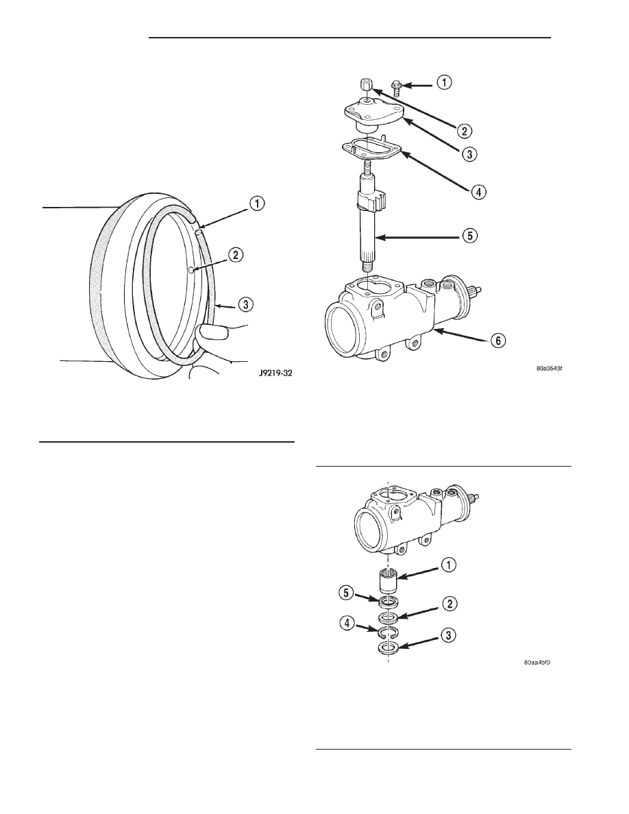
(4) Install retaining ring with open end 25 mm (1

inch) from access hole (Fig. 3).

(5) Adjust pitman arm shaft, refer to Over-Center

Adjustment.

PITMAN SHAFT

REMOVAL

(1) Clean exposed end of pitman shaft and housing

with a wire brush.

(2) Remove preload adjuster nut (Fig. 4).
(3) Rotate the stub shaft with a 12 point socket

from stop to stop and count the number of turns.

(4) Center the stub shaft by rotating it from the

stop 1/2 of the total amount of turns.

(5) Remove side cover bolts and remove side cover,

gasket and pitman shaft as an assembly (Fig. 4).

NOTE: The pitman shaft will not clear the housing if
it is not centered.

(6) Remove pitman shaft from the side cover.
(7) Remove dust seal from the housing with a seal

pick (Fig. 5).

CAUTION: Use care not to score the housing bore
when prying out seals and washer.

(8) Remove retaining ring with snap ring pliers.
(9) Remove washer from the housing.

Fig. 3 Installing The Retaining Ring

1 - RING CAP
2 - PUNCH ACCESS HOLE
3 - RETAINER RING

Fig. 4 Side Cover and Pitman Shaft

1 - SIDE COVER BOLTS
2 - PRELOAD ADJUSTER NUT
3 - SIDE COVER
4 - GASKET SEAL
5 - PITMAN SHAFT GEAR
6 - HOUSING ASSEMBLY

Fig. 5 Pitman Shaft Seals & Bearing

1 - BEARING
2 - WASHER
3 - DUST SEAL
4 - RETAINER
5 - OIL SEAL

19a - 2

STEERING

R1

STEERING GEAR HOUSING PLUG (Continued)

(10) Remove oil seal from the housing with a seal

pick.

(11) Remove pitman shaft bearing from housing

with a bearing driver and handle (Fig. 6).

INSTALLATION

(1) Install pitman shaft bearing into housing with

a bearing driver and handle.

(2) Coat the oil seal and washer with special

grease supplied with the new seal.

(3) Install the oil seal with a driver and handle.
(4) Install backup washer.
(5) Install the retainer ring with snap ring pliers.
(6) Coat the dust seal with special grease sup-

plied with the new seal.

(7) Install dust seal with a driver and handle.
(8) Install pitman shaft to side cover by screwing

shaft in until it fully seats to side cover.

(9) Install preload adjuster nut. Do not tighten

nut until after Over-Center Rotation Torque
adjustment has been made.

(10) Install gasket to side cover and bend tabs

around edges of side cover (Fig. 4).

(11) Install pitman shaft assembly and side cover

to housing.

(12) Install side cover bolts and tighten to 60 N·m

(44 ft. lbs.).

(13) Perform over-center rotation torque adjust-

ment.

SPOOL VALVE

REMOVAL

(1) Remove lock nut (Fig. 7).
(2) Remove adjuster nut with Spanner Wrench

C-4381.

(3) Remove thrust support assembly out of the

housing (Fig. 8).

(4) Pull stub shaft and valve assembly from the

housing (Fig. 9).

Fig. 6 Needle Bearing Removal

1 - REMOVER
2 - SIDE COVER AREA

Fig. 7 Lock Nut and Adjuster Nut

1 - ADJUSTER NUT
2 - STEERING GEAR
3 - LOCK NUT
4 - PUNCH

Fig. 8 Thrust Support Assembly

1 - STUB SHAFT
2 - HOUSING
3 - THRUST SUPPORT ASSEMBLY

R1

STEERING

19a - 3

PITMAN SHAFT (Continued)

(5) Remove stub shaft from valve assembly by

lightly tapping shaft on a block of wood to loosen
shaft. Then disengage stub shaft pin from hole in
spool valve and separate the valve assembly from
stub shaft (Fig. 10).

(6) Remove spool valve from valve body by pulling

and rotating the spool valve from the valve body (Fig.
11).

(7) Remove spool valve O-ring and valve body

teflon rings and O-rings underneath the teflon rings
(Fig. 12).

(8) Remove the O-ring between the worm shaft

and the stub shaft.

Fig. 9 Valve Assembly With Stub Shaft

1 - THRUST SUPPORT
2 - LOCK NUT
3 - ADJUSTER NUT
4 - STUB SHAFT
5 - VALVE ASSEMBLY
6 - GEAR

Fig. 10 Stub Shaft

1 - STUB SHAFT
2 - VALVE BODY
3 - HOLE IN SPOOL
4 - SHAFT PIN
5 - 6mm (1/4

9

)

Fig. 11 Spool Valve

1 - SPOOL VALVE
2 - ROTATE VALVE TO REMOVE
3 - VALVE BODY

Fig. 12 Valve Seals

1 - O-RING SEALS

19a - 4

STEERING

R1

SPOOL VALVE (Continued)

INSTALLATION

NOTE: Clean and dry all components, then lubricate
with power steering fluid.

(1) Install spool valve spool O-ring.
(2) Install spool valve in valve body by pushing

and rotating. Hole in spool valve for stub shaft pin
must be accessible from opposite end of valve body.

(3) Install stub shaft in valve spool and engage

locating pin on stub shaft into spool valve hole (Fig.
13).

NOTE: Notch in stub shaft cap must fully engage
valve body pin and seat against valve body shoulder.

(4) Install O-rings and teflon rings over the

O-rings on valve body.

(5) Install O-ring into the back of the stub shaft

cap (Fig. 14).

(6) Install stub shaft and valve assembly in the

housing. Line up worm shaft to slots in the valve
assembly.

(7) Install thrust support assembly.

NOTE: The thrust support is serviced as an assem-
bly. If any component of the thrust support is dam-
aged the assembly must be replaced.

(8) Install adjuster nut and lock nut.
(9) Adjust Thrust Bearing Preload and Over-Cen-

ter Rotating Torque.

WORM SHAFT

REMOVAL

(1) Remove housing end plug.
(2) Remove rack piston plug (Fig. 15).
(3) Remove side cover and pitman shaft.

(4) Turn stub shaft COUNTERCLOCKWISE until

the rack piston begins to come out of the housing.

Fig. 13 Stub Shaft Installation

1 - NOTCH IN CAP
2 - VALVE BODY PIN

Fig. 14 Stub Shaft Cap O-Ring

1 - VALVE BODY
2 - STUB SHAFT CAP
3 - O-RING

Fig. 15 Rack Piston End Plug

1 - EXTENSION
2 - END PLUG
3 - RACK PISTON
4 - RATCHET

R1

STEERING

19a - 5

SPOOL VALVE (Continued)


Content   ..  583  584  585  586   ..