Dodge Dakota (R1). Manual - part 583


  Index      Dodge     Dodge Dakota (R1) - service repair manual 2000 year


Search            


Content   ..  581  582  583  584   ..


Dodge Dakota (R1). Manual - part 583


(6) Set wheel toe pattern,(Refer to 2 - SUSPENSION/

WHEEL ALIGNMENT - STANDARD PROCEDURE).

INSTALLATION - OUTER TIE ROD END

NOTE: Do not twist the boot at anytime during
removal or installation.

(1) Thread the outer tie rod end onto the inner tie

rod, to it’s original position.

(2) Install the outer tie rod end into the steering

knuckle.

(3) Tighten the ball stud nut on the steering

knuckle to 88 N·m (65 ft. lbs.).

(4) Tighten jam nut to 75 N·m (55 ft. lbs.).
(5) Set wheel toe pattern,(Refer to 2 - SUSPENSION/

WHEEL ALIGNMENT - STANDARD PROCEDURE).

BOOT SEAL

DESCRIPTION

The boot seal is a bellows type seal the protects

dirt and contaminates from entering the open gears
of the rack and pinion unit.

OPERATION

The boot seal operates with the inward and out-

ward motions of the rack and pinion, If the seal is
worn or ripped in any way it must be replaced.

REMOVAL

(1) Loosen the jam nut to remove the outer tie rod

end,(Refer to 19 - STEERING/LINKAGE/TIE ROD
END - REMOVAL).

(2) Remove the jam nut.

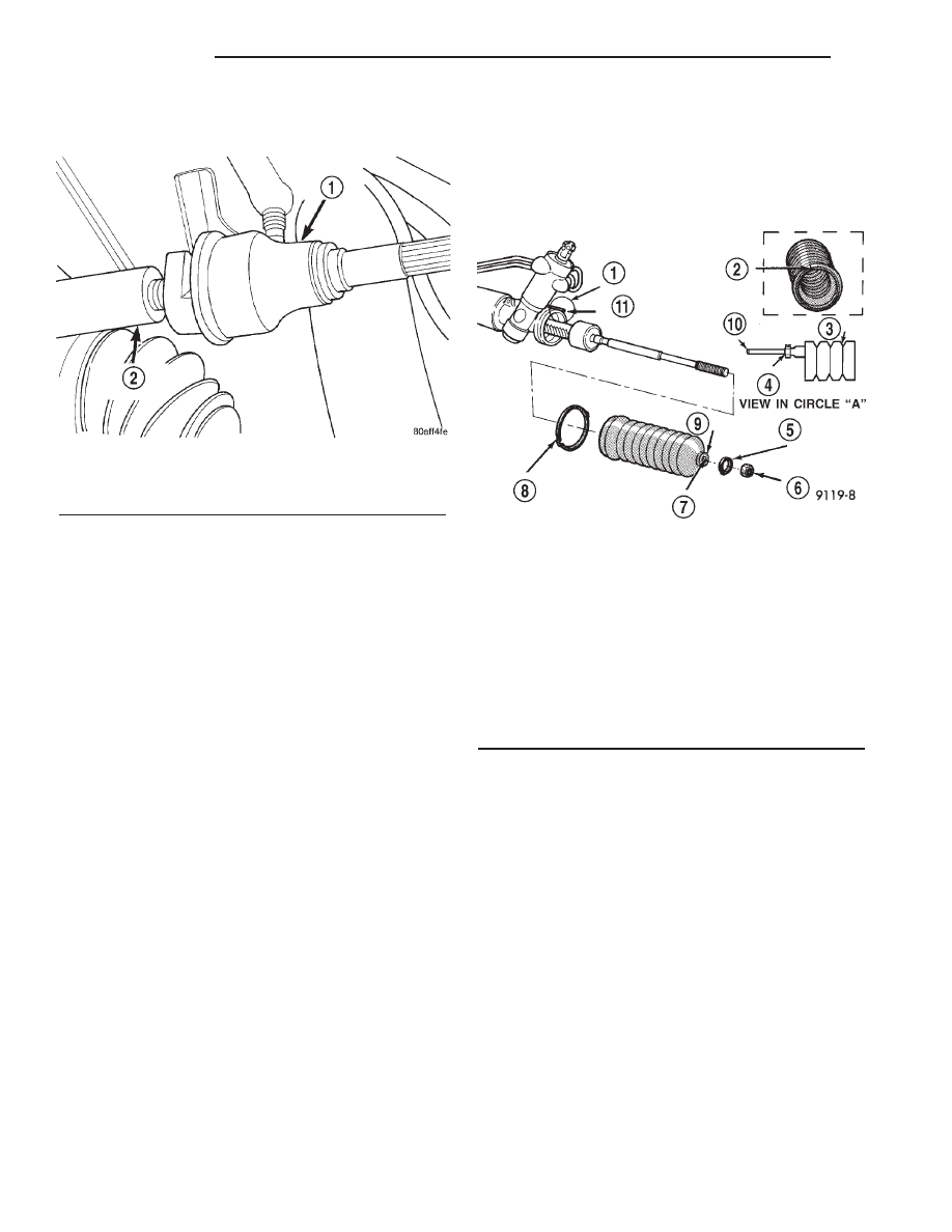
(3) Remove the outer clamp from the rubber boot

(Fig. 4).

(4) Remove the boot inner clamp.
(5) On 4x2 vehicles mark the breather tube loca-

tion on steering gear before removing the rubber boot
(Fig. 4).

INSTALLATION

(1) Lubricate the boot outer groove (tie rod) with

silicone type lubricant. Ensure that the boot is not
twisted.

(2) On 4x2 vehicles align the breather tube with

the reference mark on the steering gear.

(3) Position and align the new boot over the hous-

ing.

(4) Install inner clamp on the rubber boot.
(5) Install the snorkel clamp on 4x2 vehicles.
(6) Install outer clamp on the inner tie rod.
(7) Install the jam nut and the outer tie rod

end,(Refer to 19 - STEERING/LINKAGE/TIE ROD
END - INSTALLATION).

(8) Perform a wheel alignment,(Refer to 2 - SUS-

PENSION/WHEEL

ALIGNMENT

-

STANDARD

PROCEDURE).

Fig. 3 Inner Tie Rod

1 - INNER TIE ROD
2 - CENTER LINK

Fig. 4 Boot Seal - 4x2

1 - CIRCLE “A”
2 - MARK BREATHER TUBE LOCATION
3 - BOOT
4 - SNORKEL CLAMP
5 - BOOT CLAMP (OUTER)
6 - JAM NUT
7 - USE LUBE HERE
8 - BOOT CLAMP (INNER)
9 - BOOT SEAL
10 - BREATHER TUBE
11 - BREATHER TUBE

19 - 18

LINKAGE

AN

TIE ROD END (Continued)

PUMP

TABLE OF CONTENTS

page

page

PUMP

DESCRIPTION . . . . . . . . . . . . . . . . . . . . . . . . . . . 19
OPERATION. . . . . . . . . . . . . . . . . . . . . . . . . . . . . 19
DIAGNOSIS AND TESTING . . . . . . . . . . . . . . . . . 19

PUMP LEAKAGE . . . . . . . . . . . . . . . . . . . . . . . 19

STANDARD PROCEDURE . . . . . . . . . . . . . . . . . . 20

POWER STEERING PUMP - INITIAL

OPERATION . . . . . . . . . . . . . . . . . . . . . . . . . . . 20

REMOVAL . . . . . . . . . . . . . . . . . . . . . . . . . . . . . . 20
INSTALLATION. . . . . . . . . . . . . . . . . . . . . . . . . . . 21
SPECIFICATIONS . . . . . . . . . . . . . . . . . . . . . . . . 22
SPECIAL TOOLS . . . . . . . . . . . . . . . . . . . . . . . . . 22

FLUID COOLER

REMOVAL . . . . . . . . . . . . . . . . . . . . . . . . . . . . . . 23

INSTALLATION. . . . . . . . . . . . . . . . . . . . . . . . . . . 23

HOSES

REMOVAL . . . . . . . . . . . . . . . . . . . . . . . . . . . . . . 23
INSTALLATION. . . . . . . . . . . . . . . . . . . . . . . . . . . 23

POWER STEERING PRESSURE SWITCH

DESCRIPTION . . . . . . . . . . . . . . . . . . . . . . . . . . . 23
OPERATION. . . . . . . . . . . . . . . . . . . . . . . . . . . . . 23
REMOVAL . . . . . . . . . . . . . . . . . . . . . . . . . . . . . . 24
INSTALLATION. . . . . . . . . . . . . . . . . . . . . . . . . . . 24

PULLEY

REMOVAL . . . . . . . . . . . . . . . . . . . . . . . . . . . . . . 24
INSTALLATION. . . . . . . . . . . . . . . . . . . . . . . . . . . 24

PUMP

DESCRIPTION

The pump is connected to the steering gear via the

pressure hose and the return hose. The pump shaft
has a pressed-on pulley that is belt driven by the
crankshaft pulley.

Trailer tow option vehicles are equipped with a

power steering pump oil cooler. On the 5.2L and 5.9L
the oil cooler is mounted to the engine block. On the
4.7L the oil cooler is mounted to the power steering
pump.

NOTE: Power steering pumps are not interchange-
able with pumps installed on other vehicles.

OPERATION

Hydraulic pressure is provided for the power steer-

ing gear by the belt driven power steering pump (Fig.
1) and (Fig. 2). The power steering pumps are con-
stant flow rate and displacement, vane-type pumps.

DIAGNOSIS AND TESTING - PUMP LEAKAGE

The pump is serviced as an assembly and should

not be disassembled. Plastic pump reservoirs can be
replace and the reservoir O-ring.

Check for leaks in the following areas:
• Pump shaft seal behind the pulley

• Pump to reservoir O-ring

• Reservoir cap

• Pressure and return lines

• Flow control valve fitting

Fig. 1 Power Steering Pump - 5.2L & 5.9L

1 - RESERVOIR CAP AND DIPSTICK
2 - RESERVOIR

AN

PUMP

19 - 19

STANDARD PROCEDURE - POWER STEERING
PUMP - INITIAL OPERATION

WARNING:

THE

FLUID

LEVEL

SHOULD

BE

CHECKED WITH ENGINE OFF TO PREVENT INJURY
FROM MOVING COMPONENTS.

CAUTION: Use MOPAR Power Steering Fluid or
equivalent. Do not use automatic transmission fluid
and do not overfill.

Wipe filler cap clean, then check the fluid level.

The dipstick should indicate COLD when the fluid is
at normal temperature.

(1) Turn steering wheel all the way to the left
(2) Fill the pump fluid reservoir to the proper level

and let the fluid settle for at least two (2) minutes.

(3) Raise the front wheels off the ground.
(4) Slowly turn the steering wheel lock-to-lock 20

times with the engine off while checking the fluid
level.

NOTE: Vehicles with long return lines or oil coolers
turn wheel 40 times.

(5) Start the engine. With the engine idling main-

tain the fluid level.

(6) Lower the front wheels and let the engine idle

for two minutes.

(7) Turn the steering wheel in both direction and

verify power assist and quiet operation of the pump.

If the fluid is extremely foamy or milky looking,

allow the vehicle to stand a few minutes and repeat
the procedure.

CAUTION: Do not run a vehicle with foamy fluid for
an extended period. This may cause pump damage.

REMOVAL - POWER STEERING PUMP - 4.7L

(1) Remove the serpentine drive belt, (Refer to 7 -

COOLING/ACCESSORY

DRIVE/DRIVE

BELTS

-

REMOVAL).

(2) Remove return hose from the pump reservoir

and drain the pump.

(3) Remove power steering pressure switch connec-

tor and remove pressure line from the bottom of the
pump.

(4) Remove the oil cooler mounting bolt from the

pump bracket if equipped.

(5) Remove

3

pump

mounting

bolts

(Fig.

3)

through pulley access holes.

(6) Remove the pump from the left cylinder head.

Fig. 2 Power Steering Pump - 4.7L

1 - PUMP
2 - RESERVOIR
3 - PULLEY

Fig. 3 Power Steering Pump - 4.7L

1 - PUMP
2 - MOUNTING BOLTS

19 - 20

PUMP

AN

PUMP (Continued)

REMOVAL - POWER STEERING PUMP - 5.2L &
5.9L

(1) Remove the serpentine drive belt, (Refer to 7 -

COOLING/ACCESSORY

DRIVE/DRIVE

BELTS

-

REMOVAL).

(2) Clamp the fluid return hose and disconnect the

hoses from the power steering pump. Cap the fit-
tings.

(3) Remove battery ground cable and bracket bolts.
(4) Remove the pump assembly (Fig. 4).

(5) Remove the pump pulley, (Refer to 19 -

STEERING/PUMP/PULLEY - REMOVAL). This will
allow access to the pump attaching screws.

(6) Remove the pump bracket bolts (Fig. 5) and

remove the bracket.

INSTALLATION - POWER STEERING PUMP -
4.7L

(1) Align the pump with the mounting holes in the

left cylinder head.

(2) Install 3 pump mounting bolts through the pul-

ley access holes. Tighten the bolts to 28 N·m (21 ft.
lbs.).

(3) Install the oil cooler to the pump bracket if

equipped. Install the oil cooler mounting bolt.

(4) Install the pressure line and return hose to the

pump. Tighten the pressure line to 35 N·m (25 ft.
lbs.).

(5) Install power steering pressure switch connec-

tor.

(6) Install the serpentine drive belt, (Refer to 7 -

COOLING/ACCESSORY

DRIVE/DRIVE

BELTS

-

INSTALLATION).

(7) Fill the power steering pump, (Refer to 19 -

STEERING/PUMP - STANDARD PROCEDURE).

INSTALLATION - POWER STEERING PUMP -
5.2L & 5.9L

(1) Install the bracket on the pump and tighten

bolts to 41 N·m (30 ft. lbs.).

(2) Install the pump pulley, (Refer to 19 - STEER-

ING/PUMP/PULLEY - INSTALLATION).

(3) Install pump assembly on the engine block and

tighten the bolts to 41 N·m (30 ft. lbs.).

(4) Install the battery ground wire and tighten nut

to 41 N·m (30 ft. lbs.).

(5) Connect the fluid hoses to the pump.
(6) Install the serpentine drive belt, (Refer to 7 -

COOLING/ACCESSORY

DRIVE/DRIVE

BELTS

-

INSTALLATION).

(7) Fill the reservoir with power steering fluid,

(Refer to 19 - STEERING/PUMP - STANDARD PRO-
CEDURE).

Fig. 4 Pump Assembly

1 - PUMP ASSEMBLY
2 - BOLTS

Fig. 5 Pump Mounting Bracket

1 - PULLEY
2 - PUMP BRACKET
3 - STEERING PUMP
4 - BOLT

AN

PUMP

19 - 21

PUMP (Continued)


Content   ..  581  582  583  584   ..