Dodge Dakota (R1). Manual - part 582
(4) Remove the power steering lines from the gear.
(Refer to 19 - STEERING/PUMP/HOSES - REMOV-
AL),(Refer
to
19
-
STEERING/PUMP/HOSES
-
REMOVAL).
(5) Remove the lower coupler bolt and slide the
coupler off the gear (Fig. 3).
(6) Remove the mounting bolts from the gear to
the front crossmember and remove the gear (Fig. 4).
REMOVAL - 4WD
(1) Raise and support the vehicle.
(2) Remove the splash shield from under the front
end to gain access to the gear.
(3) Remove the nuts from the tie rod ends.
(4) Separate tie rod ends from the knuckles with
Puller C-3894-A (Refer to 19 - STEERING/LINKAGE/
TIE ROD END - REMOVAL) (Fig. 5).
(5) Remove the power steering lines from the gear.
(Refer to 19 - STEERING/PUMP/HOSES - REMOV-
AL),(Refer
to
19
-
STEERING/PUMP/HOSES
-
REMOVAL).
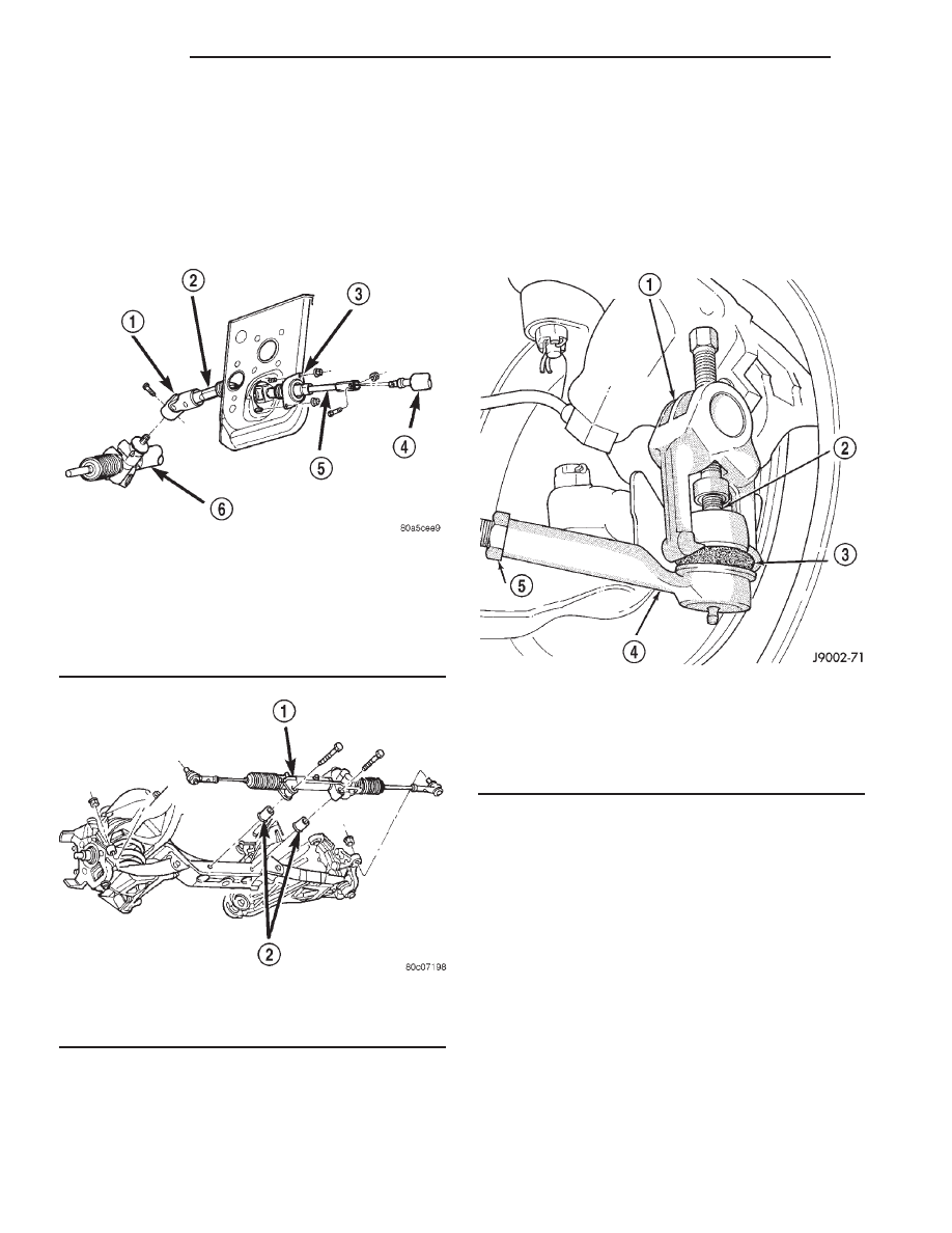
Fig. 3 Gear Coupler
1 - COUPLER
2 - LOWER SHAFT
3 - TOE PLATE
4 - STEERING COLUMN
5 - UPPER SHAFT
6 - RACK AND PINION STEERING GEAR
Fig. 4 Rack & Pinion Steering Gear - 4x2
1 - RACK AND PINION STEERING GEAR
2 - BUSHING
Fig. 5 Tie
1 - TOOL C-3894–A
2 - BALL STUD
3 - SEAL
4 - TIE-ROD END
5 - LOCK NUT
19 - 14
GEAR
AN
GEAR (Continued)