Dodge Dakota (R1). Manual - part 584
SPECIFICATIONS
TORQUE CHART
TORQUE SPECIFICATIONS
DESCRIPTION
N·m
Ft. Lbs.
In. Lbs.
5.2L/5.9L Power Steering Pump
Pump Bracket Bolts
41
30
—
5.2L/5.9L Power Steering Pump
Pump Mounting Bolts
41
30
—
5.2L/5.9L Power Steering Pump
Flow Control Valve
75
55
—
5.2L/5.9L Power Steering Pump
Pressure Line
35
25
—
4.7L Power Steering Pump
Pump Mounting Bolts
28
21
—
4.7L Power Steering Pump
Flow Control Valve
81
60
—
4.7L Power Steering Pump
Pressure Line
35
25
—
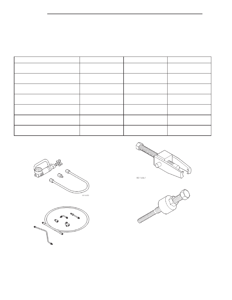
SPECIAL TOOLS
POWER STEERING PUMP
Analyzer Set, Power Steering Flow/Pressure 6815
Adapters, Power Steering Flow/Pressure Tester
6893
Puller C-4333
Installer, Power Steering Pulley C-4063–B
19 - 22
PUMP
AN