Dodge Dakota (R1). Manual - part 588
NOTE: Compressor installation requires (4) factory
installed spacers located between the engine block
and the compressor body to properly position the
compressor. The spacers containing a dowel pin
are used in the front (front of engine) mounting
location while the undoweled are used in the rear.
(6) Lift the compressor into position and install
the (4) compressor mounting bolts and spacers.
Torque the compressor mounting bolts to 41 N·m (30
ft. lbs.) (Fig. 9).
(7) Install the (2) H–Block retaining bolts thread-
ing into the compressor drive cup. Torque the bolts to
18 N·m (159 in. lbs.) (Fig. 10).
(8) Torque the H-Block intermediate shaft coupler
pinch bolt to 13.5 N·m (120 in. lbs.) (Fig. 10).
(9) Connect the compressor electrical connector.
(10) Lower the vehicle on the hoist.
(11) Remove the engine bridge fixture (Fig. 11).
(12) Torque the left front engine mount bracket
retaining bolt to 61 N·m (45 ft. lbs.).
(13) Install the power steering fluid pressure line
on the pump. Torque the nut to 28 N·m (21 ft. lbs.).
(14) Install
the
power
steering
pump
pulley.
Torque the retaining nut to 166 N·m (120 ft.lbs.).
(15) Install the accessory drive belt (Fig. 12),
(Refer to 7 - COOLING/ACCESSORY DRIVE/DRIVE
BELTS - INSTALLATION) .
(16) Install the (2) refrigerant line support bracket
bolts on the generator mounting bracket and the
water manifold. Torque bolts to 32 N·m (24 ft. lbs.).
(17) Fill the power steering fluid to specification-
,(Refer to 19 - STEERING/PUMP - STANDARD PRO-
CEDURE) .
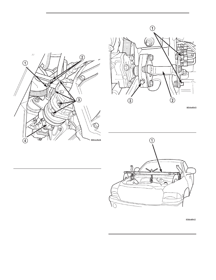
Fig. 9 Compressor Position & Orientation
1 - COMPRESSOR ELECTRICAL CONNECTOR
2 - REFRIGERANT LINE RETAINING BOLTS
3 - COMPRESSOR RETAINING BOLTS
4 - H-BLOCK
Fig. 10 Compressor Drive Assembly
1 - COMPRESSOR DRIVE CUP RETAINING BOLTS
(COMPRESSOR REMOVED)
2 - H-BLOCK ASSEMBLY
3 - INTERMEDIATE SHAFT COUPLER PINCH BOLT
Fig. 11 Engine Bridge Fixture
1 - ENGINE BRIDGE FIXTURE
19a - 14
PUMP
R1
PUMP (Continued)