Dodge Dakota (R1). Manual - part 577


  Index      Dodge     Dodge Dakota (R1) - service repair manual 2000 year


Search            


Content   ..  575  576  577  578   ..


Dodge Dakota (R1). Manual - part 577


ENGINE COOLANT
TEMPERATURE SENSOR

DESCRIPTION

The 0–5 volt input from this sensor tells the ECM

and PCM the temperature of the engine coolant.
Based on the voltage received at the ECM, it will
then determine operation of the fuel timing solenoid,
glow plug relay, electrical vacuum modulator (emis-
sion component) and generator (charging system).

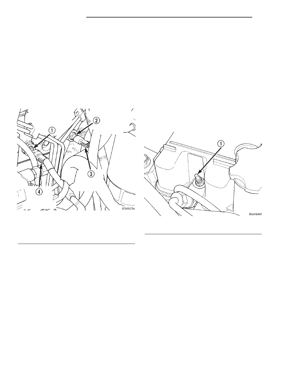
The sensor is located on the side of the #3 cylinder

head near the rear of fuel injection pump (Fig. 4).

ENGINE COOLANT TEMPERATURE SENSOR
TEST

For a list of Diagnostic Trouble Codes (DTC’s) for

certain fuel system components, refer to On-Board
Diagnostics in Group 25, Emission Control System.
To test the sensor only, refer to the following:

(1) Disconnect wire harness connector from coolant

temperature sensor.

(2) Test the resistance of the sensor with a high

input impedance (digital) volt–ohmmeter. The resis-
tance (as measured across the sensor terminals)
should be less than 1340 ohms with the engine
warm. Refer to the following Sensor Resistance
(OHMS) chart. Replace the sensor if it is not within
the range of resistance specified in the chart.

(3) Test continuity of the wire harness. Do this

between the ECM wire harness connector and the

sensor connector terminal. Also test continuity of
wire harness to the sensor connector terminal. Refer
to Group 8W for wiring connector and circuitry infor-
mation. Repair the wire harness if an open circuit is
indicated.

(4) After tests are completed, connect electrical

connector to sensor.

GLOW PLUGS

DESCRIPTION

Glow plugs are used to help start a cold or cool

engine. The plug will heat up and glow to heat the
combustion chamber of each cylinder. An individual
plug is used for each cylinder. Each plug is threaded
into the cylinder head above the fuel injector (Fig. 5).

Each plug will momentarily draw approximately 25

amps of electrical current during the initial key–on
cycle. This is on a cold or cool engine. After heating,
the current draw will drop to approximately 9–12
amps per plug.

Total momentary current draw for all four plugs is

approximately 100 amps on a cold engine dropping to
a total of approximately 40 amps after the plugs are
heated.

Electrical operation of the glow plugs are con-

trolled by the glow plug relay. Refer to the previous
Glow Plug Relay—ECM Output for additional infor-
mation.

DIAGNOSIS AND TESTNG - GLOW PLUGS

Hard starting or a rough idle after starting may be

caused by one or more defective glow plugs. Before
testing the glow plugs, a test of the glow plug relays
should be performed. This will ensure that 12V+ is

Fig. 4 Engine Coolant Temperature Sensor Location

1 - PCM ENGINE COOLANT TEMPERATURE (ECT) SENSOR
2 - ECM ENGINE COOLANT TEMPERATURE (ECT) SENSOR
3 - ECM ECT SENSOR HARNESS CONNECTOR
4 - PCM ECT SENSOR HARNESS CONNECTOR

Fig. 5 Glow Plug

1 - GLOW PLUG

14a - 22

FUEL INJECTION

R1

available at the plugs when starting the engine.
Refer to the Glow Plug Relay Test for information.

For accurate test results, the glow plugs should be

removed from the engine. The plugs must be checked
when cold. Do not check the plugs if the engine
has

recently

been

operated.

If

plugs

are

checked when warm, incorrect amp gauge
readings will result.

Use Churchill Glow Plug Tester DX.900 or an

equivalent (Fig. 6) for the following tests. This tester
is equipped with 4 timer lamps.

(1) Remove the glow plugs from the engine. Refer

to Glow Plug Removal/Installation.

(2) Attach the red lead of the tester to the 12V+

(positive) side of the battery.

(3) Attach the black lead of the tester to the 12V–

(negative) side of the battery.

(4) Fit the glow plug into the top of the tester and

secure it with the spring loaded bar (Fig. 6).

(5) Attach the third lead wire of the tester to the

electrical terminal at the end of the glow plug.

(6) When performing the test, the tester button

(Fig. 6) should be held continuously without release
for 20 seconds as indicated by the 4 timer lamps.
Each illuminated lamp represents a 5 second time
lapse.

(a) Press and hold the tester button (Fig. 6) and

note the amp gauge reading. The gauge reading
should indicate a momentary, initial current draw
(surge) of approximately 25 amps. After the initial
surge, the amp gauge reading should begin to fall
off. The glow plug tip should start to glow an
orange color after 5 seconds. If the tip did not glow
after 5 seconds, replace the glow plug. Before dis-
carding the glow plug, check the position of the cir-
cuit breaker on the bottom of the plug tester. It
may have to be reset. Reset if necessary.

(b) Continue to hold the tester button while

observing the amp gauge and the 4 timer lamps.
When all 4 lamps are illuminated, indicating a 20
second time lapse, the amp gauge reading should
indicate a 9–12 amp current draw. If not, replace
the glow plug. Refer to Glow Plug Removal/Instal-
lation.
(7) Check each glow plug in this manner using one

20 second cycle. If the glow plug is to be retested, it
must first be allowed to cool to room temperature.

WARNING:

THE

GLOW

PLUG

WILL

BECOME

EXTREMELY

HOT

(GLOWING)

DURING

THESE

TESTS. BURNS COULD RESULT IF IMPROPERLY
HANDLED. ALLOW THE GLOW PLUG TO COOL
BEFORE REMOVING FROM TESTER.

(8) Remove the glow plug from the tester.

REMOVAL

(1) Disconnect the negative battery cable at the

battery.

(2) Clean the area around the glow plug with com-

pressed air before removal.

(3) Disconnect electrical connector (Fig. 7) at glow

plug.

Fig. 6 Typical Glow Plug Tester

1 - INSERT GLOW PLUG HERE
2 - OBSERVATION WINDOW
3 - SPRING LOADED BAR
4 - TIMER LAMPS (4)
5 - TEST LEADS
6 - TESTER BUTTON

Fig. 7 Glow Plug Electrical Connector

1 - GLOW PLUG ELECTRICAL CONNECTOR

R1

FUEL INJECTION

14a - 23

GLOW PLUGS (Continued)

(4) Remove the glow plug (Fig. 8) from cylinder

head.

INSTALLATION

(1) Apply high–temperature anti–seize compound

to glow plug threads before installation

(2) Install the glow plug into the cylinder head.

Tighten to 14 N·m (123 in. lbs.) torque.

(3) Connect battery cable to battery.

GLOW PLUG RELAY

DIAGNOSIS AND TESTING - RELAYS

The following description of operation and

tests apply only to the ASD and other relays.
The terminals on the bottom of each relay are num-
bered (Fig. 9).

OPERATION

• Terminal number 30 is connected to battery volt-

age. For both the ASD and other relays, terminal 30
is connected to battery voltage at all times.

• The ECM grounds the coil side of the relay

through terminal number 85.

• Terminal number 86 supplies voltage to the coil

side of the relay.

• When the PCM de-energizes the ASD and other

relays, terminal number 87A connects to terminal 30.
This is the Off position. In the off position, voltage is
not supplied to the rest of the circuit. Terminal 87A
is the center terminal on the relay.

• When the ECM energizes the ASD and other

relays, terminal 87 connects to terminal 30. This is
the On position. Terminal 87 supplies voltage to the
rest of the circuit.

TESTING

The following procedure applies to the ASD and

other relays.

(1) Remove relay from connector before testing.
(2) With the relay removed from the vehicle, use

an ohmmeter to check the resistance between termi-
nals 85 and 86. The resistance should be between 75
±5 ohms.

(3) Connect the ohmmeter between terminals 30

and 87A. The ohmmeter should show continuity
between terminals 30 and 87A.

(4) Connect the ohmmeter between terminals 87

and 30. The ohmmeter should not show continuity at
this time.

(5) Connect one end of a jumper wire (16 gauge or

smaller) to relay terminal 85. Connect the other end
of the jumper wire to the ground side of a 12 volt
power source.

(6) Connect one end of another jumper wire (16

gauge or smaller) to the power side of the 12 volt
power source. Do not attach the other end of the
jumper wire to the relay at this time.

WARNING: DO NOT ALLOW OHMMETER TO CON-
TACT TERMINALS 85 OR 86 DURING THIS TEST.

(7) Attach the other end of the jumper wire to

relay terminal 86. This activates the relay. The ohm-
meter should now show continuity between relay ter-
minals 87 and 30. The ohmmeter should not show
continuity between relay terminals 87A and 30.

(8) Disconnect jumper wires.

Fig. 8 Glow Plug

1 - GLOW PLUG

Fig. 9 Glow Plug Relay Location

1 - MOUNTING BOLT
2 - GLOW PLUG RELAY
3 - ELECTRICAL CONNECTOR

14a - 24

FUEL INJECTION

R1

GLOW PLUGS (Continued)

(9) Replace the relay if it did not pass the continu-

ity and resistance tests. If the relay passed the tests,
it operates properly. Check the remainder of the ASD
and other relay circuits. Refer to group 8W, Wiring
Diagrams.

ACCELERATOR PEDAL
POSITION SENSOR

ACCELERATOR PEDAL

REMOVAL

(1) Disconnect electrical connector.
(2) Remove accelerator pedal mounting bracket

nuts.

(3) Remove accelerator pedal assembly.

INSTALLATION

(1) Place accelerator pedal assembly over studs

protruding from floor pan. Tighten mounting nuts to
5 N·m (46 in. lbs.) torque.

(2) Connect electrical connector.
(3) Before starting the engine, operate the acceler-

ator pedal to check for any binding.

FUEL INJECTOR

DESCRIPTION-FUEL INJECTORS

Four fuel injectors are used on each engine. Of

these four, two different types are used. The fuel
injector used on cylinder number one is equipped
with a fuel injector sensor (Fig. 10). The other three
fuel injectors are identical. Do not place the fuel
injector equipped with the fuel injector sensor
into any other location except the cylinder
number one position.

OPERATION-FUEL INJECTOR FIRING
SEQUENCE

1–3–4–2

FUEL INJECTOR TEST

The fuel injection nozzels, located in the engine

cylinder head, spray fuel under high pressure into
the individual combustion chambers. Pressurized
fuel, delivered by the fuel injection pump, unseats a
spring-loaded needle valve inside the injector, and
the fuel is atomized as it escapes through the injector
opening into the engine’s combustion chamber. If the
fuel injector does not operate properly, the engine
may misfire, or cause other driveability problems.

A leak in the injection pump–to–injector high–pres-

sure fuel line can cause many of the same symptoms

as a malfunctioning injector. Inspect for a leak in the
high–pressure lines before checking for a malfunc-
tioning fuel injector.

WARNING: THE INJECTION PUMP SUPPLIES HIGH–
PRESSURE FUEL OF UP TO APPROXIMATELY
45,000 KPA (6526 PSI) TO EACH INDIVIDUAL INJEC-
TOR THROUGH THE HIGH–PRESSURE LINES. FUEL
UNDER THIS AMOUNT OF PRESSURE CAN PENE-
TRATE THE SKIN AND CAUSE PERSONAL INJURY.
WEAR SAFETY GOGGLES AND ADEQUATE PRO-
TECTIVE CLOTHING. AVOID CONTACT WITH FUEL
SPRAY WHEN BLEEDING HIGH–PRESSURE FUEL
LINES.

WARNING: DO NOT BLEED AIR FROM THE FUEL
SYSTEM OF A HOT ENGINE. DO NOT ALLOW FUEL
TO SPRAY ONTO THE EXHAUST MANIFOLD WHEN
BLEEDING AIR FROM THE FUEL SYSTEM.

To determine which fuel injector is malfunctioning,

run the engine and loosen the high–pressure fuel line
nut at the injector (Fig. 11). Listen for a change in
engine speed. If engine speed drops, the injector was
operating normally. If engine speed remains the
same, the injector may be malfunctioning. After test-
ing, tighten the line nut to 19 N·m (14 ft. lbs.)
torque. Test all injectors in the same manner one at
a time.

Once an injector has been found to be malfunction-

ing, remove it from the engine and test it. Refer to
the Removal/Installation section of this group for pro-
cedures.

Fig. 10 Needle Movement Sensor Location

1 - NEEDLE MOVEMENT SENSOR
2 - FUEL INJECTOR (NUMBER 1 CYLINDER ONLY)
3 - COPPER WASHER
4 - SENSOR CONNECTOR

R1

FUEL INJECTION

14a - 25

GLOW PLUG RELAY (Continued)


Content   ..  575  576  577  578   ..