Dodge Dakota (R1). Manual - part 575
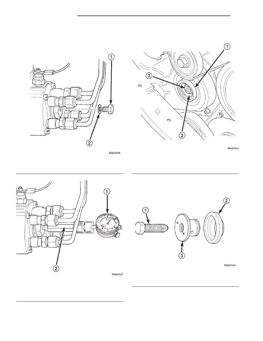
(12) Remove access plug and plug washer at rear
of pump (Fig. 24). Thread special dial indicator and
adapter tool VM.1011 (Fig. 25)into this opening.
Hand tighten only.
(13) Slightly rotate the engine in a counter-clock-
wise direction until the dial gauge indicator stops
moving (20°-25° before TDC).
(14) Remove injection pump drive gear nut (Fig.
26).
(15) A special
3–piece
gear
removal
tool
set
VM.1003 (Fig. 27) must be used to remove the injec-
tion pump drive gear from the pump shaft.
(a) Thread the adapter (Fig. 28) into the timing
cover.
(b) Thread the gear puller into the injection
pump drive gear (Fig. 28). This tool is also used to
hold the gear in synchronization during pump
removal.
Fig. 24 Access Plug at Rear of Pump
1 - ACCESS PLUG
2 - WASHER
Fig. 25 Installing Dial Indicator and Special Adapter
Tools
1 - DIAL INDICATOR TOOL
2 - ADAPTER TOOL VM.1011
Fig. 26 Removing Pump Drive Gear Nut
1 - TIMING GEAR COVER
2 - INJECTION PUMP GEAR
3 - PUMP GEAR NUT
Fig. 27 Pump Gear Tools
1 - DRIVE BOLT
2 - TIMING COVER ADAPTER
3 - GEAR PULLER
14a - 14
FUEL DELIVERY
R1
FUEL INJECTION PUMP (Continued)