Dodge Dakota (R1). Manual - part 576


  Index      Dodge     Dodge Dakota (R1) - service repair manual 2000 year


Search            


Content   ..  574  575  576  577   ..


Dodge Dakota (R1). Manual - part 576


types of clamps may cut into the hoses and cause
fuel leaks.

Where a rubber hose is joined to a metal tube

(staked), do not attempt to repair. Replace entire
line/tube assembly.

Use new original equipment type hose clamps.

Tighten hose clamps to 2 N·m (20 in. lbs.) torque.

HIGH-PRESSURE FUEL LINES

DESCRIPTION

CAUTION: The high–pressure fuel lines must be
held securely in place in their holders. The lines
cannot contact each other or other components. Do
not attempt to weld high–pressure fuel lines or to
repair lines that are damaged. Only use the recom-
mended lines when replacement of high–pressure
fuel line is necessary.

High–pressure fuel lines deliver fuel under pres-

sure of up to approximately 45,000 kPa (6526 PSI)
from the injection pump to the fuel injectors. The
lines expand and contract from the high–pressure
fuel pulses generated during the injection process. All
high–pressure fuel lines are of the same length and
inside diameter. Correct high–pressure fuel line
usage and installation is critical to smooth engine
operation.

WARNING:

USE

EXTREME

CAUTION

WHEN

INSPECTING FOR HIGH–PRESSURE FUEL LEAKS.
INSPECT FOR HIGH–PRESSURE FUEL LEAKS WITH
A SHEET OF CARDBOARD. HIGH FUEL INJECTION
PRESSURE CAN CAUSE PERSONAL INJURY IF
CONTACT IS MADE WITH THE SKIN.

DIAGNOSIS AND TESTING - HIGH-PRESSURE
FUEL LINE

High–pressure fuel line leaks can cause starting

problems and poor engine performance.

WARNING: DUE TO EXTREME FUEL PRESSURES OF
UP TO 45,000 KPA (6526 PSI), USE EXTREME CAU-
TION WHEN INSPECTING FOR HIGH–PRESSURE
FUEL LEAKS. DO NOT GET YOUR HAND, OR ANY
PART OF YOUR BODY NEAR A SUSPECTED LEAK.
INSPECT FOR HIGH–PRESSURE FUEL LEAKS WITH
A SHEET OF CARDBOARD. HIGH FUEL INJECTION
PRESSURE CAN CAUSE PERSONAL INJURY IF
CONTACT IS MADE WITH THE SKIN.

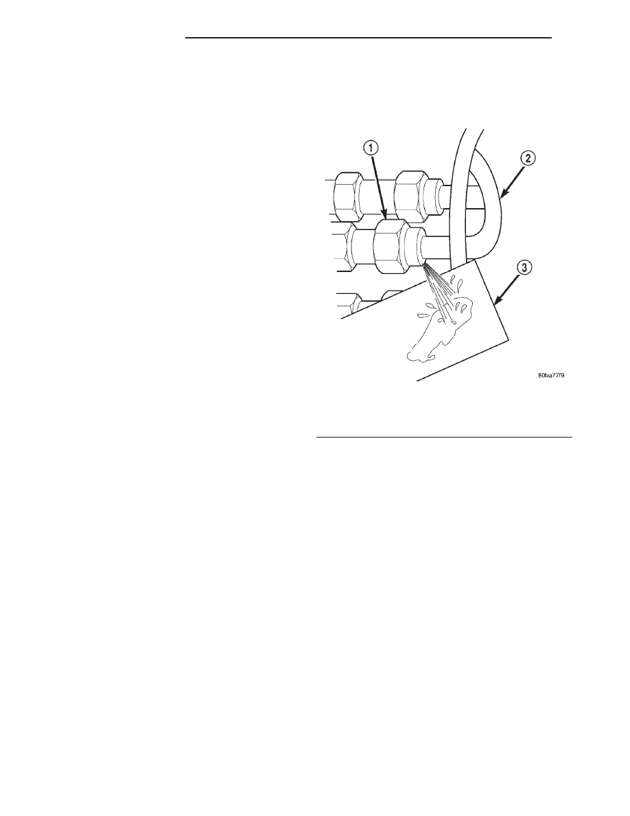
Start the engine. Move the cardboard over the

high–pressure fuel lines and check for fuel spray onto
the cardboard (Fig. 33). If a high–pressure line con-
nection is leaking, bleed the system and tighten the

connection. Refer to the Air Bleed Procedure in this
group for procedures. Replace damaged, restricted or
leaking high–pressure fuel lines with the correct
replacement line.

CAUTION: The high–pressure fuel lines must be
clamped securely in the holders. The lines cannot
contact each other or other components. Do not
attempt to weld high–pressure fuel lines or to repair
lines that are damaged. Only use the recommended
lines when replacement of high–pressure fuel line
is necessary.

FUEL SHUT DOWN SOLENOID

DESCRIPTION

The fuel shutdown solenoid is controlled and

operated by the ECM.

The fuel shutdown (shut-off) solenoid is used to

electrically shut off the diesel fuel supply to the high-
pressure

fuel

injection

pump.

The

solenoid

is

mounted to the rear of the injection pump.

The solenoid controls starting and stopping of the

engine regardless of the position of the accelerator
pedal. When the ignition (key) switch is OFF, the
solenoid is shut off and fuel flow is not allowed to the
fuel injection pump. When the key is placed in the
ON or START positions, fuel supply is allowed at the
injection pump.

Fig. 33 Typical Fuel Pressure Test at Injection Pump

1 - FITTING
2 - HIGH PRESSURE LINE
3 - CARDBOARD

14a - 18

FUEL DELIVERY

R1

FUEL HIGH PRESSURE LINES (Continued)

FUEL INJECTION

TABLE OF CONTENTS

page

page

FUEL INJECTION

SPECIFICATIONS . . . . . . . . . . . . . . . . . . . . . . . . 19

BOOST PRESSURE SENSOR

DESCRIPTION . . . . . . . . . . . . . . . . . . . . . . . . . . . 20
DIAGNOSIS AND TESTING . . . . . . . . . . . . . . . . . 20

BOOST PRESSURE SENSOR . . . . . . . . . . . . . 20

ASD RELAY

DIAGNOSIS AND TESTING . . . . . . . . . . . . . . . . . 21

ASD RELAY . . . . . . . . . . . . . . . . . . . . . . . . . . . 21

ENGINE SPEED SENSOR

DESCRIPTION . . . . . . . . . . . . . . . . . . . . . . . . . . . 21
DIAGNOSIS AND TESTING . . . . . . . . . . . . . . . . . 21

ENGINE SPEED SENSOR . . . . . . . . . . . . . . . . 21

ENGINE COOLANT TEMPERATURE SENSOR

DESCRIPTION . . . . . . . . . . . . . . . . . . . . . . . . . . . 22
DIAGNOSIS AND TESTING . . . . . . . . . . . . . . . . . 22

ENGINE COOLANT TEMPERATURE
SENSOR TEST. . . . . . . . . . . . . . . . . . . . . . . . . 22

GLOW PLUGS

DESCRIPTION . . . . . . . . . . . . . . . . . . . . . . . . . . . 22
DIAGNOSIS AND TESTING . . . . . . . . . . . . . . . . . 22

GLOW PLUGS . . . . . . . . . . . . . . . . . . . . . . . . . 22

REMOVAL . . . . . . . . . . . . . . . . . . . . . . . . . . . . . . 23
INSTALLATION. . . . . . . . . . . . . . . . . . . . . . . . . . . 24

GLOW PLUG RELAY

DIAGNOSIS AND TESTING . . . . . . . . . . . . . . . . . 24

RELAYS . . . . . . . . . . . . . . . . . . . . . . . . . . . . . . 24

ACCELERATOR PEDAL POSITION SENSOR

REMOVAL . . . . . . . . . . . . . . . . . . . . . . . . . . . . . . 25
INSTALLATION. . . . . . . . . . . . . . . . . . . . . . . . . . . 25

FUEL INJECTOR

DESCRIPTION . . . . . . . . . . . . . . . . . . . . . . . . . . . 25
OPERATION. . . . . . . . . . . . . . . . . . . . . . . . . . . . . 25
DIAGNOSIS AND TESTING . . . . . . . . . . . . . . . . . 25

FUEL INJECTOR TEST. . . . . . . . . . . . . . . . . . . 25
NEEDLE MOVEMENT SENSOR . . . . . . . . . . . . 26

REMOVAL . . . . . . . . . . . . . . . . . . . . . . . . . . . . . . 26
INSTALLATION. . . . . . . . . . . . . . . . . . . . . . . . . . . 27

SPEED SENSOR

DIAGNOSIS AND TESTING . . . . . . . . . . . . . . . . . 27

VEHICLE SPEED SENSOR TEST . . . . . . . . . . . 27

FUEL INJECTION

SPECIFICATIONS

TORQUE SPECIFICATIONS

SPECIFICATIONS

DESCRIPTION

SPECIFICATION

Fuel Tank Capacity
Nominal refill capacities
are shown. A variation
may be observed from
vehicle to vehicle due to
manufacturing tolerances,
ambient temperatures
and refill procedures.

75 Liters (20.0 Gals.)

Idle Speed
With engine at normal
operating temperature.

750 RPM ± 25 RPM

DESCRIPTION

SPECIFICATION

Fuel Injector Firing
Sequence

1-3-4-2

FUEL SYSTEM PRESSURE

Peak Injection Pressure/
Fuel Injection Pump
Operating Pressure

40,000-45,000 kPa
(5801-6526 psi)

Opening Pressure of Fuel
Injector

16,500-17,300 kPa
(2393-2509 psi)

GLOW PLUG CURRENT DRAW

Initial Current Draw

Approximately 22-25
amps per plug.

After 20 seconds of
operation

Approximately 9-12 amps
per plug.

R1

FUEL INJECTION

14a - 19

TORQUE SPECIFICATIONS

DESCRIPTION

N·m

Ft. Lbs.

In. Lbs.

Accelerator Pedal Bracket Mounting Nuts

5

-

46

Banjo-Type Fittings

19

14

-

Engine Speed Sensor Bolts

19

14

-

Fuel Hose (Tubes) Clamps For Rubber

Hoses

2

-

20

Fuel Injector

70

52

-

Fuel Injector Line at Injector

30

22

-

Fuel Injector Line at Injection Pump

30

22

-

Fuel Injection Pump Mounting Nuts

30

22

-

Fuel Injection Pump Drive Gear

88

65

-

Fuel Line Clamp Bracket Bolts

24

18

-

Fuel Tank Nuts

11

-

100

Glow Plugs

23

-

203

Vehicle Speed Sensor Mounting Bolts

3

-

26

BOOST PRESSURE SENSOR

DESCRIPTION

The Boost Pressure Sensor is mounted to the top of

the intake manifold (Fig. 1). It is a sensor that mea-
sures both manifold vacuum and turbo boost, and it
also contains an integrated intake air temperature
sensor. The Boost Pressure Sensor takes the place of
the Mass Air Flow (MAF). In the Intake Air Temper-
ature Sensor component, there is a ceramic element
that changes its resistance based on temperature.
The ceramic element is part of an electronic circuit
connected to the PCM, and has a voltage applied to
it. The ceramic element is exposed to the air inside
the intake. This air has a cooling effect on the
ceramic element, and its resistance changes. This
causes the voltage flowing through the intake air
temperature circuit to vary. The voltage signal pro-
duced by the Intake Air Temperature Sensor changes
inversely to the temperature, and is measured by the
PCM. As a general rule, when the temperature of the
air in the intake is high, the voltage signal produced
by the Intake Air Temperature Sensor is low. The
component of the Boost Pressure Sensor that mea-
sures manifold vacuum and turbo boost produces a
voltage signal that is proportional to the pressure in
the intake manifold. When the intake manifold pres-
sure is low, the voltage is low, and when the pressure
is high, the voltage is high. The PCM uses the volt-
age signals from the Boost Pressure Sensor, and the
Intake Air Temperature Sensor to determine the
amount of air flowing through the intake manifold.

DIAGNOSIS AND TESTING - BOOST PRESSURE
SENSOR

If the boost pressure sensor fails, the PCM records

a DTC into memory and continues to operate the
engine in one of the three modes. When the PCM is
operating in this mode, a loss of power will be
present, as if the turbocharger was not operating.
The best method for diagnosing faults with the boost
pressure sensor is with the DRB III scan tool. Refer
to On-Board Diagnostics in Group 25, Emission Con-

Fig. 1 Boost Pressure Sensor Location

1 - BOOST PRESSURE SENSOR HARNESS CONNECTOR
2 - BOOST PRESSURE SENSOR

14a - 20

FUEL INJECTION

R1

FUEL INJECTION (Continued)

trol System for a list of Diagnostic Trouble Codes
(DTC’s) for certain fuel system components (Refer to
25 - EMISSIONS CONTROL/ON-BOARD DIAGNOS-
TICS - DESCRIPTION).

ASD RELAY

DIAGNOSIS AND TESTING - ASD RELAY

To perform a test of the relay and its related cir-

cuitry, refer to the DRB scan tool. To test the relay
only, refer to Relays—Operation/Testing in this sec-
tion of the group.

Diagnostic Trouble Codes: Refer to On-Board

Diagnostics in Group 25, Emission Control System
for a list of Diagnostic Trouble Codes (DTC’s) for cer-
tain fuel system components.

ENGINE SPEED SENSOR

DESCRIPTION

The engine speed sensor is mounted to the trans-

mission bellhousing at the left/rear side of the engine
block (Fig. 2).

The engine speed sensor produces its own output

signal. If this signal is not received, the ECM will not
allow the engine to start.

The engine speed sensor input is used in conjunc-

tion with the first injector sensor to establish fuel
injection pump timing.

The flywheel has four notches at its outer edge

(Fig. 3). Each notch is spaced equally every 90°. The
notches cause a pulse to be generated when they
pass under the speed sensor (Fig. 3). These pulses
are the input to the ECM. The input from this sensor
determines crankshaft position (in degrees) by moni-
toring the notches.

The sensor also generates an rpm signal to the

ECM. This signal is used as an input for the control
of the generator field, vehicle speed control, and
instrument panel mounted tachometer.

If the engine speed sensor should fail, the system

is unable to compensate for the problem and the car
will stop.

DIAGNOSIS AND TESTING - ENGINE SPEED
SENSOR

To perform a test of the engine speed sensor and

its related circuitry, refer to the Diesel Powertrain
Diagnostic Procedures Manual.

Diagnostic Trouble Codes: Refer to On-Board

Diagnostics in Group 25, Emission Control System
for a list of Diagnostic Trouble Codes (DTC’s) for cer-
tain fuel system components (Refer to 25 - EMIS-
SIONS

CONTROL/ON-BOARD

DIAGNOSTICS

-

DESCRIPTION).

Fig. 2 Engine Speed Sensor Location

1 - ENGINE SPEED SENSOR
2 - GROMMET
3 - MOUNTING BOLT(S)
4 - LEFT REAR OF ENGINE
5 - TRANSMISSION

Fig. 3 Speed Sensor Operation

1 - ENGINE SPEED SENSOR
2 - FLYWHEEL
3 - NOTCHES

R1

FUEL INJECTION

14a - 21

BOOST PRESSURE SENSOR (Continued)


Content   ..  574  575  576  577   ..