Dodge Dakota (R1). Manual - part 567


  Index      Dodge     Dodge Dakota (R1) - service repair manual 2000 year


Search            


Content   ..  565  566  567  568   ..


Dodge Dakota (R1). Manual - part 567


INSTALLATION

WARNING: THE FUEL SYSTEM IS UNDER A CON-
STANT PRESSURE EVEN WITH ENGINE TURNED
OFF.

BEFORE

SERVICING

FUEL

INJECTOR(S),

FUEL SYSTEM PRESSURE MUST BE RELEASED.

To release fuel pressure, refer to Fuel System Pres-

sure Release Procedure.

To remove one or more fuel injectors, fuel rail

assembly must be removed from engine.

(1) Apply a small amount of clean engine oil to

each fuel injector o-ring. This will help in fuel rail
installation.

(2) Install injector(s) and injector clip(s) to fuel

rail.

(3) Install fuel rail assembly. Refer to Fuel Injector

Rail Removal/Installation.

(4) Install air cleaner.
(5) Start engine and check for leaks.

FUEL PUMP RELAY

DESCRIPTION

The 5–pin, 12–volt, fuel pump relay is located in

the Power Distribution Center (PDC). Refer to the
label on the PDC cover for relay location.

OPERATION

The Powertrain Control Module (PCM) energizes

the electric fuel pump through the fuel pump relay.
The fuel pump relay is energized by first applying
battery voltage to it when the ignition key is turned
ON, and then applying a ground signal to the relay
from the PCM.

Whenever the ignition key is turned ON, the elec-

tric fuel pump will operate. But, the PCM will shut-
down the ground circuit to the fuel pump relay in
approximately 1–3 seconds unless the engine is oper-
ating or the starter motor is engaged.

REMOVAL

The fuel pump relay is located in the Power Distri-

bution Center (PDC) (Fig. 33) . Refer to label on PDC
cover for relay location.

(1) Remove PDC cover.
(2) Remove relay from PDC.
(3) Check condition of relay terminals and PDC

connector terminals for damage or corrosion. Repair
if necessary before installing relay.

(4) Check for pin height (pin height should be the

same for all terminals within the PDC connector).
Repair if necessary before installing relay.

INSTALLATION

The fuel pump relay is located in the Power Distri-

bution Center (PDC) (Fig. 33) . Refer to label on PDC
cover for relay location.

(1) Install relay to PDC.
(2) Install cover to PDC.

IDLE AIR CONTROL MOTOR

DESCRIPTION

The IAC stepper motor is mounted to the throttle

body, and regulates the amount of air bypassing the
control of the throttle plate. As engine loads and
ambient temperatures change, engine rpm changes.
A pintle on the IAC stepper motor protrudes into a
passage in the throttle body, controlling air flow
through the passage. The IAC is controlled by the
Powertrain Control Module (PCM) to maintain the
target engine idle speed.

OPERATION

At idle, engine speed can be increased by retract-

ing the IAC motor pintle and allowing more air to
pass through the port, or it can be decreased by
restricting the passage with the pintle and diminish-
ing the amount of air bypassing the throttle plate.

The IAC is called a stepper motor because it is

moved (rotated) in steps, or increments. Opening the
IAC opens an air passage around the throttle blade
which increases RPM.

The PCM uses the IAC motor to control idle speed

(along with timing) and to reach a desired MAP dur-
ing decel (keep engine from stalling).

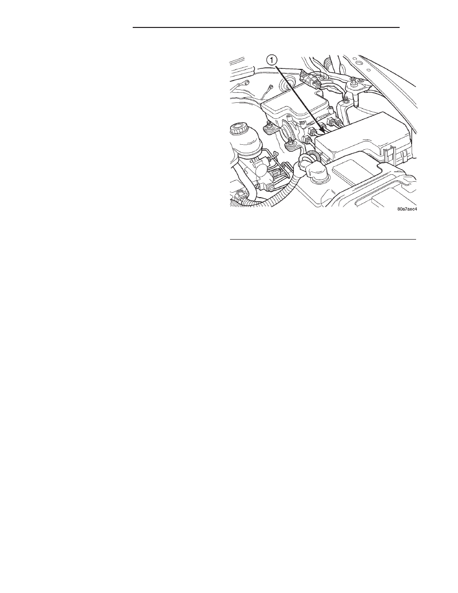
Fig. 33 Power Distribution Center (PDC)

1 - POWER DISTRIBUTION CENTER (PDC)

14 - 40

FUEL INJECTION

AN

FUEL INJECTOR (Continued)

The IAC motor has 4 wires with 4 circuits. Two of

the wires are for 12 volts and ground to supply elec-
trical current to the motor windings to operate the
stepper motor in one direction. The other 2 wires are
also for 12 volts and ground to supply electrical cur-
rent to operate the stepper motor in the opposite
direction.

To make the IAC go in the opposite direction, the

PCM just reverses polarity on both windings. If only
1 wire is open, the IAC can only be moved 1 step
(increment) in either direction. To keep the IAC
motor in position when no movement is needed, the
PCM will energize both windings at the same time.
This locks the IAC motor in place.

In the IAC motor system, the PCM will count

every step that the motor is moved. This allows the
PCM to determine the motor pintle position. If the
memory is cleared, the PCM no longer knows the
position of the pintle. So at the first key ON, the
PCM drives the IAC motor closed, regardless of
where it was before. This zeros the counter. From
this point the PCM will back out the IAC motor and
keep track of its position again.

When engine rpm is above idle speed, the IAC is

used for the following:

• Off-idle dashpot (throttle blade will close quickly

but idle speed will not stop quickly)

• Deceleration air flow control

• A/C compressor load control (also opens the pas-

sage slightly before the compressor is engaged so
that the engine rpm does not dip down when the
compressor engages)

• Power steering load control
The PCM can control polarity of the circuit to con-

trol direction of the stepper motor.

IAC Stepper Motor Program: The PCM is also

equipped with a memory program that records the
number of steps the IAC stepper motor most recently
advanced to during a certain set of parameters. For
example: The PCM was attempting to maintain a
1000 rpm target during a cold start-up cycle. The last
recorded number of steps for that may have been
125. That value would be recorded in the memory
cell so that the next time the PCM recognizes the
identical conditions, the PCM recalls that 125 steps
were required to maintain the target. This program
allows for greater customer satisfaction due to
greater control of engine idle.

Another function of the memory program, which

occurs when the power steering switch (if equipped),
or the A/C request circuit, requires that the IAC step-
per motor control engine rpm, is the recording of the
last targeted steps into the memory cell. The PCM
can anticipate A/C compressor loads. This is accom-
plished by delaying compressor operation for approx-
imately 0.5 seconds until the PCM moves the IAC

stepper motor to the recorded steps that were loaded
into the memory cell. Using this program helps elim-
inate idle-quality changes as loads change. Finally,
the PCM incorporates a

9No-Load9 engine speed lim-

iter of approximately 1800 - 2000 rpm, when it rec-
ognizes that the TPS is indicating an idle signal and
IAC motor cannot maintain engine idle.

A (factory adjusted) set screw is used to mechani-

cally limit the position of the throttle body throttle
plate. Never attempt to adjust the engine idle
speed using this screw. 
All idle speed functions are
controlled by the IAC motor through the PCM.

REMOVAL - 3.9L/5.2L/5.9L

The IAC motor is located on the back of the throt-

tle body (Fig. 34).

(1) Remove air duct at throttle body.
(2) Disconnect electrical connector from IAC motor.
(3) Remove two mounting bolts (screws) (Fig. 34).

(4) Remove IAC motor from throttle body.

REMOVAL - 4.7L

The IAC motor is located on the throttle body.
(1) Remove air duct and air resonator box at throt-

tle body.

(2) Disconnect electrical connector from IAC motor

(Fig. 54).

(3) Remove two mounting bolts (screws) (Fig. 60).
(4) Remove IAC motor from throttle body.

REMOVAL - 2.5L

The IAC motor is located on the side of the throttle

body (Fig. 35).

(1) Remove air duct at throttle body.
(2) Disconnect electrical connector from IAC motor.

Fig. 34 Mounting Bolts (Screws)—IAC Motor—3.9/

5.2/5.9L Engines

1 - MOUNTING SCREWS
2 - IDLE SPEED MOTOR

AN

FUEL INJECTION

14 - 41

IDLE AIR CONTROL MOTOR (Continued)

(3) Remove two mounting bolts (screws) (Fig. 35).
(4) Remove IAC motor from throttle body.

INSTALLATION - 3.9L/5.2L/5.9L

The IAC motor is located on the back of the throt-

tle body (Fig. 34).

(1) Install IAC motor to throttle body.
(2) Install and tighten two mounting bolts (screws)

to 7 N·m (60 in. lbs.) torque.

(3) Install electrical connector.
(4) Install air duct at throttle body.

INSTALLATION - 4.7L

(1) Install IAC motor to throttle body.
(2) Install and tighten two mounting bolts (screws)

to 7 N·m (60 in. lbs.) torque.

(3) Install electrical connector.
(4) Install air duct/air box to throttle body.

INSTALLATION - 2.5L

The IAC motor is located on the side of the throttle

body (Fig. 35).

(1) Install IAC motor to throttle body.
(2) Install and tighten two mounting bolts (screws)

to 7 N·m (60 in. lbs.) torque.

(3) Install electrical connector.
(4) Install air duct at throttle body.

INTAKE AIR TEMPERATURE
SENSOR

DESCRIPTION

The 2–wire Intake Manifold Air Temperature (IAT)

sensor is installed in the intake manifold with the
sensor element extending into the air stream.

The IAT sensor is a two-wire Negative Thermal

Coefficient (NTC) sensor. Meaning, as intake mani-
fold temperature increases, resistance (voltage) in the
sensor decreases. As temperature decreases, resis-
tance (voltage) in the sensor increases.

OPERATION

The IAT sensor provides an input voltage to the

Powertrain Control Module (PCM) indicating the
density of the air entering the intake manifold based
upon intake manifold temperature. At key-on, a
5–volt power circuit is supplied to the sensor from
the PCM. The sensor is grounded at the PCM
through a low-noise, sensor-return circuit.

The PCM uses this input to calculate the following:
• Injector pulse-width

• Adjustment of spark timing (to help prevent

spark knock with high intake manifold air-charge
temperatures)

The resistance values of the IAT sensor is the same

as for the Engine Coolant Temperature (ECT) sensor.

REMOVAL - 3.9L/5.2L/5.9L

The intake manifold air temperature sensor is

located in the front/side of the intake manifold (Fig.
36).

(1) Remove air duct at throttle body.
(2) Disconnect electrical connector at sensor (Fig.

36).

(3) Remove sensor from intake manifold.

Fig. 35 Mounting Bolts (Screws)—

IAC Motor—2.5L Engine

1 - IDLE AIR CONTROL MOTOR
2 - MOUNTING SCREWS

Fig. 36 Intake Manifold Air Temperature Sensor—

3.9/5.2/5.9L Engines—Typical

1 - INTAKE MANIFOLD AIR TEMPERATURE SENSOR
2 - ELECTRICAL CONNECTOR

14 - 42

FUEL INJECTION

AN

IDLE AIR CONTROL MOTOR (Continued)

REMOVAL - 4.7L

The Intake Manifold Air Temperature (IAT) sensor

is installed into the intake manifold plenum near the
left side of the throttle body (Fig. 37).

(1) Disconnect electrical connector from sensor.
(2) Remove sensor from intake manifold.

REMOVAL - 2.5L

The intake manifold air temperature sensor is

located in the intake manifold (Fig. 38).

(1) Remove air duct at throttle body.
(2) Disconnect electrical connector at sensor (Fig.

38).

(3) Remove sensor from intake manifold.

INSTALLATION - 3.9L/5.2L/5.9L

The intake manifold air temperature sensor is

located in the front/side of the intake manifold (Fig.
36).

(1) Install sensor to intake manifold. Tighten to 28

N·m (20 ft. lbs.) torque.

(2) Install electrical connector.
(3) Install air duct at throttle body.

INSTALLATION - 4.7L

(1) Install sensor into intake manifold. Tighten

sensor to 28 N·m (20 ft. lbs.) torque.

(2) Connect electrical connector to sensor.

INSTALLATION - 2.5L

The intake manifold air temperature sensor is

located in the intake manifold (Fig. 38).

(1) Install sensor to intake manifold. Tighten to 28

N·m (20 ft. lbs.) torque.

(2) Install electrical connector.
(3) Install air duct at throttle body.

MAP SENSOR

DESCRIPTION - EXCEPT 4.7L

The Manifold Absolute Pressure (MAP) sensor is

attached to the side of the engine throttle body with
2 screws. The sensor is connected to the throttle body
with a rubber L-shaped fitting.

Fig. 37 Intake Manifold Air Sensor Location—4.7L

V-8 Engine

1 - THROTTLE BODY
2 - TPS
3 - IAC MOTOR
4 - IAT SENSOR
5 - MOUNTING SCREWS

Fig. 38 Intake Manifold Air Temperature Sensor—

2.5L Engine

1 - FUEL PRESSURE TEST PORT
2 - ELECTRICAL CONNECTOR
3 - INTAKE MANIFOLD AIR TEMPERATURE SENSOR
4 - FUEL INJECTOR

AN

FUEL INJECTION

14 - 43

INTAKE AIR TEMPERATURE SENSOR (Continued)


Content   ..  565  566  567  568   ..