Dodge Dakota (R1). Manual - part 553


  Index      Dodge     Dodge Dakota (R1) - service repair manual 2000 year


Search            


Content   ..  551  552  553  554   ..


Dodge Dakota (R1). Manual - part 553


STANDARD PROCEDURE - FRAME SERVICE

SAFETY PRECAUTIONS AND WARNINGS

WARNING: USE EYE PROTECTION WHEN GRIND-
ING OR WELDING METAL, SERIOUS EYE INJURY
CAN RESULT. BEFORE PROCEEDING WITH FRAME
REPAIR INVOLVING GRINDING OR WELDING, VER-
IFY THAT VEHICLE FUEL SYSTEM IS NOT LEAKING
OR IN CONTACT WITH REPAIR AREA, PERSONAL
INJURY CAN RESULT. DO NOT ALLOW OPEN
FLAME TO CONTACT PLASTIC BODY PANELS.
FIRE

OR

EXPLOSION

CAN

RESULT.

WHEN

WELDED FRAME COMPONENTS ARE REPLACED,
100% PENETRATION WELD MUST BE ACHIEVED
DURING

INSTALLATION.

IF

NOT,

DANGEROUS

OPERATING CONDITIONS CAN RESULT. STAND
CLEAR OF CABLES OR CHAINS ON PULLING
EQUIPMENT

DURING

FRAME

STRAIGHTENING

OPERATIONS, PERSONAL INJURY CAN RESULT.
DO NOT VENTURE UNDER A HOISTED VEHICLE
THAT IS NOT SUPPORTED ON SAFETY STANDS,
PERSONAL INJURY CAN RESULT.

CAUTION: Do not reuse damaged fasteners, quality
of repair would be suspect. Do not drill holes in top
or bottom frame rail flanges, frame rail failure can
result. Do Not use softer than Grade 5 bolts to
replace production fasteners, loosening or failure
can result. When using heat to straighten frame
components do not exceed 566°C (1050°F), metal
fatigue can result. Welding the joints around riveted
cross members and frame side rails can weaken
frame.

FRAME STRAIGHTENING

When necessary, a conventional frame that is bent

or twisted can be straightened by application of heat.
The temperature must not exceed 566°C (1050°F).
The metal will have a dull red glow at the desired
temperature.

Excessive

heat

will

decrease

the

strength of the metal and result in a weakened
frame.

Welding the joints around riveted cross members

and frame side rails is not recommended.
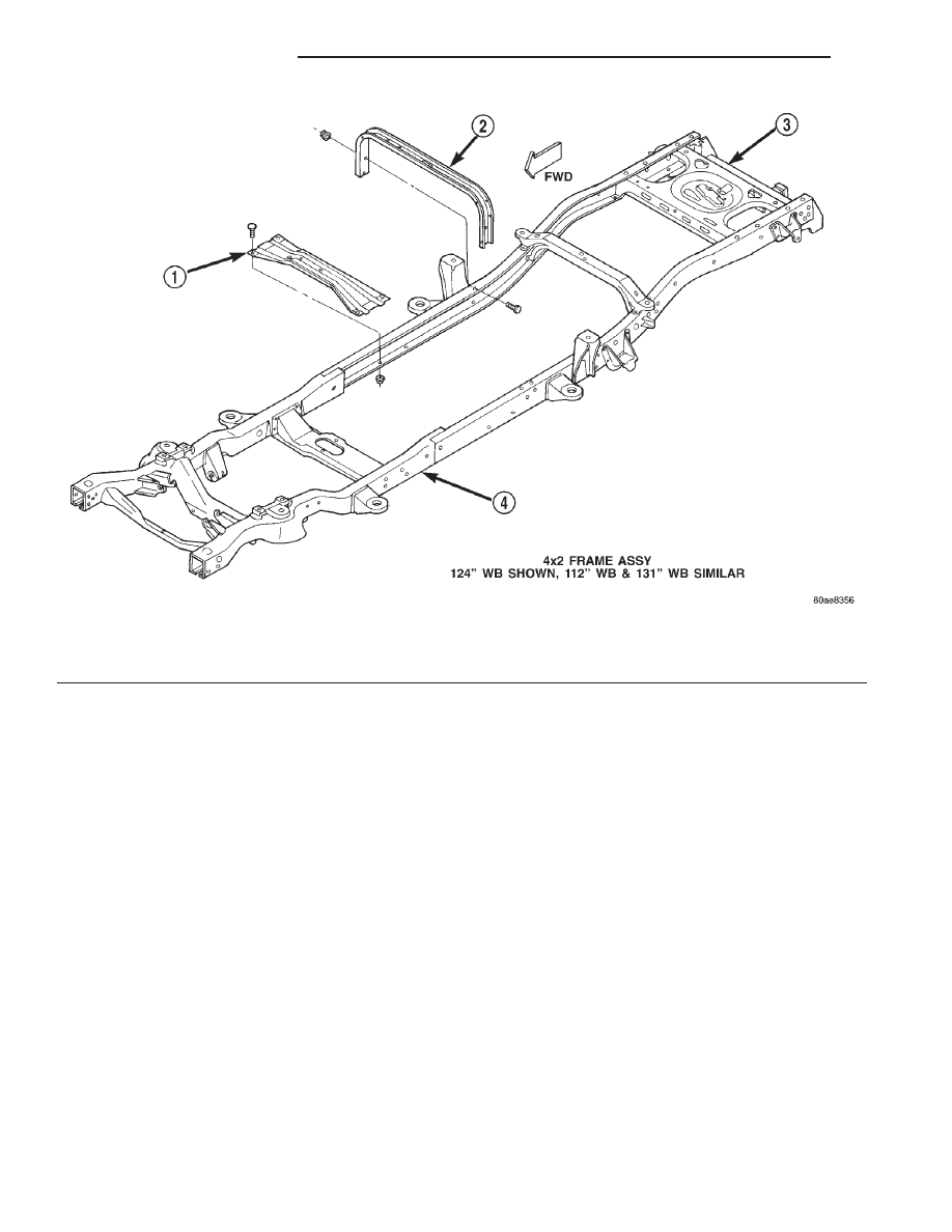
Fig. 3 4X2 Frame

1 - CENTER BEARING CROSSMEMBER
2 - FUEL TANK CROSSMEMBER

3 - TRAILER HITCH
4 - FRAME

13 - 4

FRAME & BUMPERS

AN

FRAME (Continued)

A straightening repair process should be limited to

frame members that are not severely damaged. The
replacement bolts, nuts and rivets that are used to
join the frame members should conform to the same
specifications as the original bolts, nuts and rivets.

FRAME REPAIRS

DRILLING HOLES

Do not drill holes in frame side rail top and bottom

flanges, metal fatigue can result causing frame fail-
ure. Holes drilled in the side of the frame rail must
be at least 38 mm (1.5 in.) from the top and bottom
flanges.

Additional drill holes should be located away from

existing holes.

WELDING

Use MIG, TIG or arc welding equipment to repair

welded frame components.

Frame components that have been damaged should

be inspected for cracks before returning the vehicle
to use. If cracks are found in accessible frame com-
ponents perform the following procedures.

(1) Drill a hole at each end of the crack with a 3

mm (O.125 in.) diameter drill bit.

(2) Using a suitable die grinder with 3 inch cut off

wheel, V-groove the crack to allow 100% weld pene-
tration.

(3) Weld the crack.
(4) If necessary when a side rail is repaired, grind

the weld smooth and install a reinforcement channel
(Fig. 8) over the repaired area.

Fig. 4 4X4 Frame

1 - FUEL TANK CROSSMEMBER
2 - TRAILER HITCH

3 - FRAME

AN

FRAME & BUMPERS

13 - 5

FRAME (Continued)

NOTE: If a reinforcement channel is required, the
top and bottom flanges should be 0.250 inches nar-
rower than the side rail flanges. Weld only in the
areas indicated (Fig. 8).

FRAME FASTENERS

Bolts, nuts and rivets can be used to repair frames

or to install a reinforcement section on the frame.
Bolts can be used in place of rivets. When replacing
rivets with bolts, install the next larger size diameter
bolt to assure proper fit. If necessary, ream the hole
out just enough to sufficiently receive the bolt.

Conical-type washers are preferred over the split-

ring type lock washers. Normally, grade-5 bolts are
adequate for frame repair. Grade-3 bolts or softer
should not be used. 
Tightening bolts/nuts with the
correct torque, refer to the Introduction Group at the
front of this manual for tightening information.

Fig. 5 Cab Mounts

1 - FLOOR PAN
2 - REAR CAB ISOLATOR
3 - UNDER CAB ISOLATOR
4 - UNDER CAB ISOLATOR

5 - FRAME
6 - FRONT CAB ISOLATOR

Fig. 6 Radiator Closure Panel

1 - RADIATOR CLOSURE PANEL
2 - FRAME
3 - ISOLATOR
4 - ISOLATOR

13 - 6

FRAME & BUMPERS

AN

FRAME (Continued)

Fig. 7 Cargo Box

1 - CARGO BOX
2 - FRAME RAIL

Fig. 8 Frame Reinforcement

1 - .250 IN FROM EDGE
2 - TOP FLANGE
3 - BOTTOM FLANGE
4 - FRAME RAIL
5 - FRAME REPAIR REINFORCEMENT

AN

FRAME & BUMPERS

13 - 7

FRAME (Continued)


Content   ..  551  552  553  554   ..