Dodge Dakota (R1). Manual - part 552


  Index      Dodge     Dodge Dakota (R1) - service repair manual 2000 year


Search            


Content   ..  550  551  552  553   ..


Dodge Dakota (R1). Manual - part 552


(18) Install the cowl grille (Fig. 9) (Refer to 23 -

BODY/EXTERIOR/COWL GRILLE - INSTALLATION).

(19) Raise the vehicle on the hoist.
(20) Install the oil return line on the turbocharger

(Fig. 10). Torque the bolts to 11 N·m (97 in. lbs.).

(21) Install the lower front splash shield.
(22) Lower the vehicle on the hoist.
(23) A new turbocharger must be pre-lubricated

with clean engine oil before engine start up. Pour
10–20 cc (.5–1 ounce) of oil into the oil pressure sup-
ply fitting hole.

(24) Rotate the turbine wheel to allow the oil to

enter the turbocharger.

(25) Install the turbocharger oil supply line on the

turbocharger. Torque banjo bolt to 27 N·m (20 ft. lbs.).

(26) Fill the cooling system (Refer to 7 - COOLING

- STANDARD PROCEDURE).

(27) Install both of the wiper arms on the vehicle.

Refer to Group 8K, Wiper and Washer Systems for
the procedure.

(28) Connect the negative battery cable.
(29) Start the engine and check for leaks.

CHARGE AIR COOLER

DESCRIPTION

On 2.5L turbo diesel engine equipped vehicles, the

charge air cooler (intercooler) is bolted to and sup-
ported by the radiator. If either one of these compo-
nents requires replacement they must be removed
from the vehicle as an assembly and disassembled on
a bench. For the charge air cooler (intercooler)
replacement procedure (Refer to 7 - COOLING/EN-
GINE/RADIATOR - REMOVAL) and (Refer to 7 -
COOLING/ENGINE/RADIATOR - INSTALLATION).
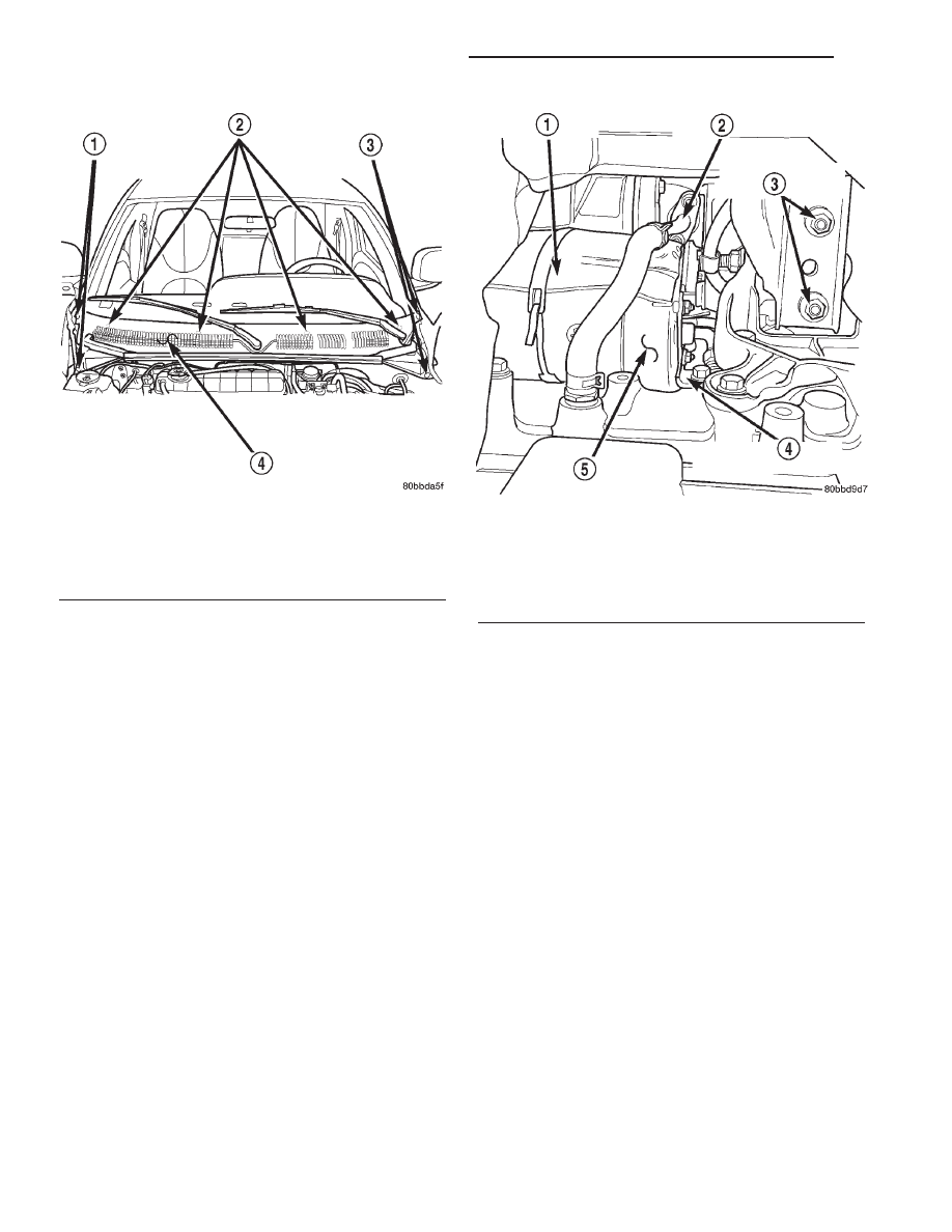
Fig. 9 Cowl Grille

1 - PUSHPINS
2 - COWL GRILLE RETAINING NUTS
3 - PUSHPINS
4 - COWL GRILLE

Fig. 10 Turbocharger Oil Return Line Position

1 - STARTER MOTOR HEATSHIELD
2 - TURBOCHARGER OIL RETURN LINE
3 - RIGHT ENGINE MOUNT RETAINING NUTS
4 - STARTER MOTOR SUPPORT BRACKET
5 - STARTER MOTOR

11a - 6

EXHAUST SYSTEM AND TURBOCHARGER

R1

EXHAUST MANIFOLD AND TURBOCHARGER (Continued)

FRAME & BUMPERS

TABLE OF CONTENTS

page

page

BUMPERS

DESCRIPTION . . . . . . . . . . . . . . . . . . . . . . . . . . . . 1
OPERATION . . . . . . . . . . . . . . . . . . . . . . . . . . . . . 1

FRONT BUMPER

REMOVAL . . . . . . . . . . . . . . . . . . . . . . . . . . . . . . . 1
INSTALLATION. . . . . . . . . . . . . . . . . . . . . . . . . . . . 2

FRONT FASCIA

REMOVAL . . . . . . . . . . . . . . . . . . . . . . . . . . . . . . . 2
INSTALLATION. . . . . . . . . . . . . . . . . . . . . . . . . . . . 2

REAR BUMPER

REMOVAL . . . . . . . . . . . . . . . . . . . . . . . . . . . . . . . 2
INSTALLATION. . . . . . . . . . . . . . . . . . . . . . . . . . . . 3

FRAME

DESCRIPTION . . . . . . . . . . . . . . . . . . . . . . . . . . . . 3
OPERATION . . . . . . . . . . . . . . . . . . . . . . . . . . . . . 3
STANDARD PROCEDURE . . . . . . . . . . . . . . . . . . . 4

FRAME SERVICE. . . . . . . . . . . . . . . . . . . . . . . . 4

SPECIFICATIONS . . . . . . . . . . . . . . . . . . . . . . . . . 8

FRONT SKID PLATE

REMOVAL . . . . . . . . . . . . . . . . . . . . . . . . . . . . . . 11
INSTALLATION . . . . . . . . . . . . . . . . . . . . . . . . . . . 11

FUEL TANK SKID PLATE

REMOVAL . . . . . . . . . . . . . . . . . . . . . . . . . . . . . . 12
INSTALLATION. . . . . . . . . . . . . . . . . . . . . . . . . . . 12

TRAILER HITCH

REMOVAL . . . . . . . . . . . . . . . . . . . . . . . . . . . . . . 12
INSTALLATION. . . . . . . . . . . . . . . . . . . . . . . . . . . 12

VALANCE PANEL

REMOVAL . . . . . . . . . . . . . . . . . . . . . . . . . . . . . . 13
INSTALLATION. . . . . . . . . . . . . . . . . . . . . . . . . . . 13

TRANSFER CASE SKID PLATE

REMOVAL . . . . . . . . . . . . . . . . . . . . . . . . . . . . . . 13
INSTALLATION. . . . . . . . . . . . . . . . . . . . . . . . . . . 13

BUMPERS

DESCRIPTION

Bumpers are used at the front and rear of the

vehicle. Bumpers are incorporated into the design of
the front and rear fascias. They are mounted to the
frame with brackets and may contain some lamp ele-
ments.

OPERATION

Bumpers are designed to protect the exterior sheet-

metal in low impact situations. The bumpers are
attached to the frame and provide mounting points
for some optional accessories such as fog lights and
tow hooks.

FRONT BUMPER

REMOVAL

(1) Open hood.
(2) Support front bumper on a suitable lifting

device.

(3) Disengage wire connectors from fog lamps, if

equipped.

(4) Disengage

push-in

fasteners

attaching

air

deflector to bottom of bumper fascia.

(5) Pull the front wheelhouse liner back at the

bumper and remove bolts attaching outer bumper
brackets to frame rail (Fig. 1).

(6) Remove the bolts attaching the bumper to the

inner bumper bracket.

(7) Separate front bumper with outer bracket

attached from vehicle.

AN

FRAME & BUMPERS

13 - 1

INSTALLATION

When the front bumper is installed, there should

be a 19 mm gap between the bumper and front
fender.

(1) Place the bumper on a suitable lifting device

and position the bumper at the vehicle.

(2) Install the bolts attaching front bumper to

inner bumper bracket. Tighten to 94 N·m (70 ft. lbs.)
torque.

(3) Install the bolts attaching outer bumper brack-

ets to the frame rail. Tighten to 94 N·m (70 ft. lbs.)
torque. Ensure front wheelhouse liners are positioned
correctly behind bumper.

(4) Engage

wire

connectors

to

fog

lamps,

if

equipped.

(5) Install push-in fasteners attaching air deflector

to front bumper fascia.

(6) Remove lifting device.
(7) Close hood.

FRONT FASCIA

REMOVAL

(1) Remove the front bumper.
(2) Remove the bolts attaching the fascia to the

bumper.

(3) Separate fascia from bumper.

INSTALLATION

(1) Position fascia on bumper.
(2) Install the bolts attaching the fascia to the

bumper.

(3) Install the front bumper.

REAR BUMPER

REMOVAL

(1) Support rear bumper on a suitable lifting

device.

(2) Remove bolts attaching inner bumper brackets

to frame rails (Fig. 2).

Fig. 1 Front Bumper

1 - FOG LAMP
2 - FRONT BUMPER
3 - OUTER BUMPER BRACKET
4 - U-NUT

5 - FRAME
6 - INNER BUMPER BRACKET
7 - FASCIA BRACKET

13 - 2

FRAME & BUMPERS

AN

FRONT BUMPER (Continued)

(3) Disengage license plate lamp wire connector

from body wire harness, if equipped.

(4) Separate rear bumper from vehicle.

INSTALLATION

(1) Place bumper on a suitable lifting device and

raise into position.

(2) Engage license plate lamp wire connector from

body wire harness, if equipped.

(3) Install bolts attaching inner bumper brackets

to frame rails. Tighten to 94 N·m (70 ft. lbs.) torque.

(4) Remove lifting device.

FRAME

DESCRIPTION

Dakota trucks have a ladder-type frame with Box-

section front rails, dropped center section and open-
channel side rails in the rear (Fig. 3) and (Fig. 4).

Cross members attached to the frame side rails

with rivets, welds or bolts form a ladder-type con-
struction. Additionally, the Dakota Quad Cab uses a
mass dampener located between the frame rails,
immediately

forward

of

the

rear

bumper.

This

damper is used to address NVH issues. The cab is
isolated from the frame with rubber load cushions
(Fig. 5) and (Fig. 6) with through-bolts. The cargo
box or bed is attached to the frame with bolts (Fig. 7)
(Refer to 23 - BODY/EXTERIOR/CARGO BOX -
REMOVAL).

OPERATION

The frame is designed to absorb and dissipate flex-

ing and twisting due to acceleration, braking, corner-
ing and road surface variances without bending when
subjected to normal driving conditions. The frame is
the mounting platform for the following systems and
components:

• Front and rear suspension systems.

• Engine, transmission, and transfer case.

• Steering gear and linkage.

• Exhaust system and heat shields.

• Fuel cell and fuel line tubing.

• Front end sheet metal and radiator closure

panel.

• Skid plate.

• Passenger cab.

• Cargo box or bed.

• Spare tire winch.

• Front and rear bumper systems.

Fig. 2 Rear Bumper

1 - REAR BUMPER
2 - OUTER BRACKET
3 - INNER BRACKET
4 - FRAME

AN

FRAME & BUMPERS

13 - 3

REAR BUMPER (Continued)


Content   ..  550  551  552  553   ..