Dodge Dakota (R1). Manual - part 550


  Index      Dodge     Dodge Dakota (R1) - service repair manual 2000 year


Search            


Content   ..  548  549  550  551   ..


Dodge Dakota (R1). Manual - part 550


INSTALLATION

(1)

Position the heat shields to the floor pan or

the frame and install the screws and/or nuts.

(2) Tighten the nuts and/or screws to specification.

Refer to Specifications in this section for correct
torque values.

(3) Lower the vehicle.

INTERMEDIATE PIPE

REMOVAL

(1) Raise and support the vehicle.
(2) Saturate the clamp nuts with Mopar

t Rust

Penetrant. Allow 5 minutes for penetration.

(3) Remove the front and rear clamp nuts.
(4) It may be necessary to loosen other sections of

the exhaust system to remove the extension pipe.

INSTALLATION

(1) Position the extension pipe in the muffler and

the catalytic converter flange.

(2) If other sections of the exhaust system where

loosened in removal, refer to the section for tighten-
ing procedures.

(3) Install the clamps and nuts (Fig. 4). Tighten

the nuts to 47 N·m (35 ft. lbs.) torque.

(4) Lower the vehicle.
(5) Start the engine, inspect for exhaust leaks and

exhaust system contact with the body panels. Adjust
the alignment, if needed.

MUFFLER

DESCRIPTION

All engines use a stainless steel muffler to control

exhaust noise levels and exhaust back pressure.

REMOVAL

CAUTION: When servicing or replacing exhaust
system components, disconnect the oxygen sensor
connector(s). Allowing the exhaust to hang by the
oxygen sensor wires will damage the harness
and/or sensor.

(1) Raise and support the vehicle.
(2) Saturate the clamp nuts with Mopar

t Rust

Penetrant. Allow 5 minutes for penetration.

(3) Remove the muffler clamp nuts from the front

hanger and the rear muffler to tailpipe connection
(Fig. 23).

(4) Disconnect the muffler from the tailpipe. The

tailpipe should be supported when the muffler is dis-
connected.

(5) Remove the muffler from the extension pipe or

catalytic converter flange.

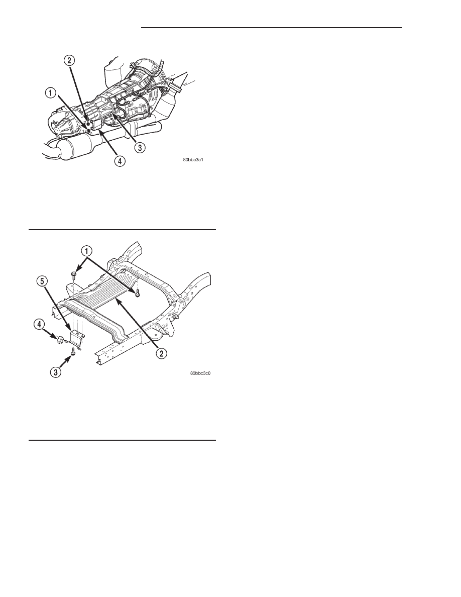
Fig. 21 Electrical Connector Heat Shield—45RFE

Transmission

1 - BOLT RETAINER
2 - LOCKNUT
3 - STUDS
4 - HEAT SHIELD

Fig. 22 Muffler Heat Shield—4 Door Cab

1 - SCREW SELF TAPPING
2 - MUFFLER HEAT SHIELD
3 - SCREW SELF TAPPING
4 - ISOLATOR
5 - HANGER BRACKET

11 - 12

EXHAUST SYSTEM

AN

HEAT SHIELDS (Continued)

INSTALLATION

CAUTION: When servicing or replacing exhaust
system components, disconnect the oxygen sensor
connector(s). Allowing the exhaust to hang by the
oxygen sensor wires will damage the harness
and/or sensor.

(1) If the upper front muffler support was removed

(Fig. 23), install the bolts into the frame. Tighten the
bolts to 23 N·m (200 in. lbs.) torque. The insulators
slip over the ends of the upper and lower muffler
hangers.

(2) Install the muffler into the extension pipe or

catalytic converter flange. Install the clamp and
tighten the nuts finger tight.

(3) Install the tailpipe into the rear of the muffler.
(4) Tighten the clamp nuts on the front and rear

muffler hangers to 41 N·m (30 ft. lbs.) torque.

(5) Lower the vehicle.
(6) Start the engine, inspect for exhaust leaks and

exhaust system contact with the body panels. Adjust
the alignment, if needed.

TAILPIPE - 2.5L/3.9L/4.7L

DESCRIPTION

The tailpipe is made of stainless steel and attaches

to the muffler.

REMOVAL

CAUTION: When servicing or replacing exhaust
system components, disconnect the oxygen sensor
connector(s). Allowing the exhaust to hang by the
oxygen sensor wires will damage the harness
and/or sensor.

(1) Raise and support the vehicle.
(2) Saturate the clamp nuts with Mopar

t Rust

Penetrant. Allow 5 minutes for penetration.

(3) Remove muffler to tailpipe exhaust clamp.
(4) Remove the tailpipe from the front and rear

insulators (Fig. 24).

(5) Remove the tailpipe.

Fig. 23 Muffler and Tailpipe Assembly

1 - TAILPIPE HANGER
2 - MUFFLER AND TAILPIPE
3 - FRONT MUFFLER HANGER
4 - REAR MUFFLER HANGER

Fig. 24 Tailpipe and Hangers—2.5L/3.9L/4.7L

1 - INSULATORS
2 - TAILPIPE
3 - CLAMP
4 - MUFFLER

AN

EXHAUST SYSTEM

11 - 13

MUFFLER (Continued)

INSTALLATION

CAUTION: When servicing or replacing exhaust
system components, disconnect the oxygen sensor
connector(s). Allowing the exhaust to hang by the
oxygen sensor wires will damage the harness
and/or sensor.

(1) Position the tailpipe into the muffler. Install

the nuts onto the clamp bolt finger tight.

(2) Install the tailpipe into the insulators.
(3) Position tailpipe and tighten the muffler rear

clamp nuts to 47 N·m (35 ft. lbs.) torque.

(4) Lower the vehicle.
(5) Start the engine, inspect for exhaust leaks and

exhaust system contact with the body panels. Adjust
the alignment, if needed.

TAILPIPE - 5.9L

DESCRIPTION

The tailpipe is made of stainless steel and attaches

to the muffler.

REMOVAL

CAUTION: When servicing or replacing exhaust
system components, disconnect the oxygen sensor
connector(s). Allowing the exhaust to hang by the
oxygen sensor wires will damage the harness
and/or sensor.

(1) Raise and support the vehicle.
(2) Saturate the clamp nuts with Mopar

t Rust

Penetrant. Allow 5 minutes for penetration.

(3) Remove muffler to tailpipe exhaust clamp.
(4) Remove the tailpipe from the front and rear

insulators (Fig. 25).

(5) Remove the tailpipe.

INSTALLATION

CAUTION: When servicing or replacing exhaust
system components, disconnect the oxygen sensor
connector(s). Allowing the exhaust to hang by the
oxygen sensor wires will damage the harness
and/or sensor.

(1) Position the tailpipe into the muffler. Install

the nuts onto the clamp bolt finger tight.

(2) Install the tailpipe into the insulators.
(3) Position tailpipe and tighten the muffler rear

clamp nuts to 47 N·m (35 ft. lbs.) torque.

(4) Lower the vehicle.
(5) Start the engine, inspect for exhaust leaks and

exhaust system contact with the body panels. Adjust
the alignment, if needed.

Fig. 25 Tailpipe and Hangers—5.9L R/T

1 - HANGER BRACKETS
2 - ISOLATOR
3 - TAILPIPE

11 - 14

EXHAUST SYSTEM

AN

TAILPIPE - 2.5L/3.9L/4.7L (Continued)

EXHAUST SYSTEM AND TURBOCHARGER

TABLE OF CONTENTS

page

page

EXHAUST SYSTEM AND TURBOCHARGER

SPECIFICATIONS . . . . . . . . . . . . . . . . . . . . . . . . . 1

TURBOCHARGER SYSTEM

DESCRIPTION . . . . . . . . . . . . . . . . . . . . . . . . . . . . 1
OPERATION . . . . . . . . . . . . . . . . . . . . . . . . . . . . . 2

EXHAUST MANIFOLD AND TURBOCHARGER

REMOVAL . . . . . . . . . . . . . . . . . . . . . . . . . . . . . . . 4

CLEANING. . . . . . . . . . . . . . . . . . . . . . . . . . . . . . . 5
INSTALLATION. . . . . . . . . . . . . . . . . . . . . . . . . . . . 5

CHARGE AIR COOLER

DESCRIPTION . . . . . . . . . . . . . . . . . . . . . . . . . . . . 6

EXHAUST SYSTEM AND
TURBOCHARGER

SPECIFICATIONS

TORQUE SPECIFICATIONS

DESCRIPTION

Torque

EGR Attaching Bolts

27 N·m

EGR Tube Nut

34 N·m

EGR Tube Flange Bolts

27 N·m

Exhaust Manifold
Nuts

32 N·m

Exhaust Manifold
Heat Shield Bolts

11 N·m

Exhaust Pipe Support
Clamp Bolts

22.5 N·m

Exhaust Pipe Support
Clamp Screw

22.5 N·m

Intake Elbow to Intake
Manifold Bolts

11 N·m

Intake Manifold
Nuts

32 N·m

Muffler-to-Exhaust Pipe
Clamp Nuts

43 N·m

Tail Pipe Clamp
Hanger bolt

22.5 N·m

DESCRIPTION

Torque

Turbocharger-to-
Exhaust manifold
Nuts

32 N·m

Turbocharger
Oil Feed Line

27.4 N·m

Turbocharger Down
Pipe-to-Exhaust Pipe
Bolts/Nuts

22.5 N·m

Turbocharger Down
Pipe-to-Turbocharger
Bolts

27 N·m

TURBOCHARGER SYSTEM

DESCRIPTION

CAUTION: The turbocharger is a performance part
and must not be tampered with. The wastegate
bracket is an integral part of the turbocharger. Tam-
pering with the wastegate components can reduce
durability by increasing cylinder pressure and ther-
mal loading due to incorrect inlet and exhaust man-
ifold pressure. Poor fuel economy and failure to
meet regulatory emissions laws may result. Increas-
ing the turbocharger boost WILL NOT increase
engine power.

The turbocharger is an exhaust-driven super-

charger which increases the pressure and density of
the air entering the engine. With the increase of air
entering the engine, more fuel can be injected into
the cylinders, which creates more power during com-
bustion.

R1

EXHAUST SYSTEM AND TURBOCHARGER

11a - 1


Content   ..  548  549  550  551   ..