Dodge Dakota (R1). Manual - part 551
The turbocharger assembly consists of four (4)
major component systems (Fig. 1) (Fig. 2):
• Turbine section
• Compressor section
• Bearing housing
• Wastegate
OPERATION
Exhaust gas pressure and energy drive the tur-
bine, which in turn drives a centrifugal compressor
that compresses the inlet air, and forces the air into
the engine through the charge air cooler and plumb-
ing. Since heat is a by-product of this compression,
the air must pass through a charge air cooler to cool
the incoming air and maintain power and efficiency.
Increasing air flow to the engine provides:
• Improved engine performance
• Lower exhaust smoke density
• Improved operating economy
• Altitude compensation
• Noise reduction.
The turbocharger also uses a wastegate (Fig. 3),
which regulates intake manifold air pressure and
prevents over boosting at high engine speeds. When
the wastegate valve is closed, all of the exhaust gases
flow through the turbine wheel. As the intake mani-
fold pressure increases, the wastegate actuator opens
the valve, diverting some of the exhaust gases away
from the turbine wheel. This limits turbine shaft
speed and air output from the impeller.
The turbocharger is lubricated by engine oil that is
pressurized, cooled, and filtered. The oil is delivered
to the turbocharger by a supply line that is tapped
into the oil filter head. The oil travels into the bear-
ing housing, where it lubricates the shaft and bear-
ings (Fig. 4). A return pipe at the bottom of the
bearing housing, routes the engine oil back to the
crankcase.
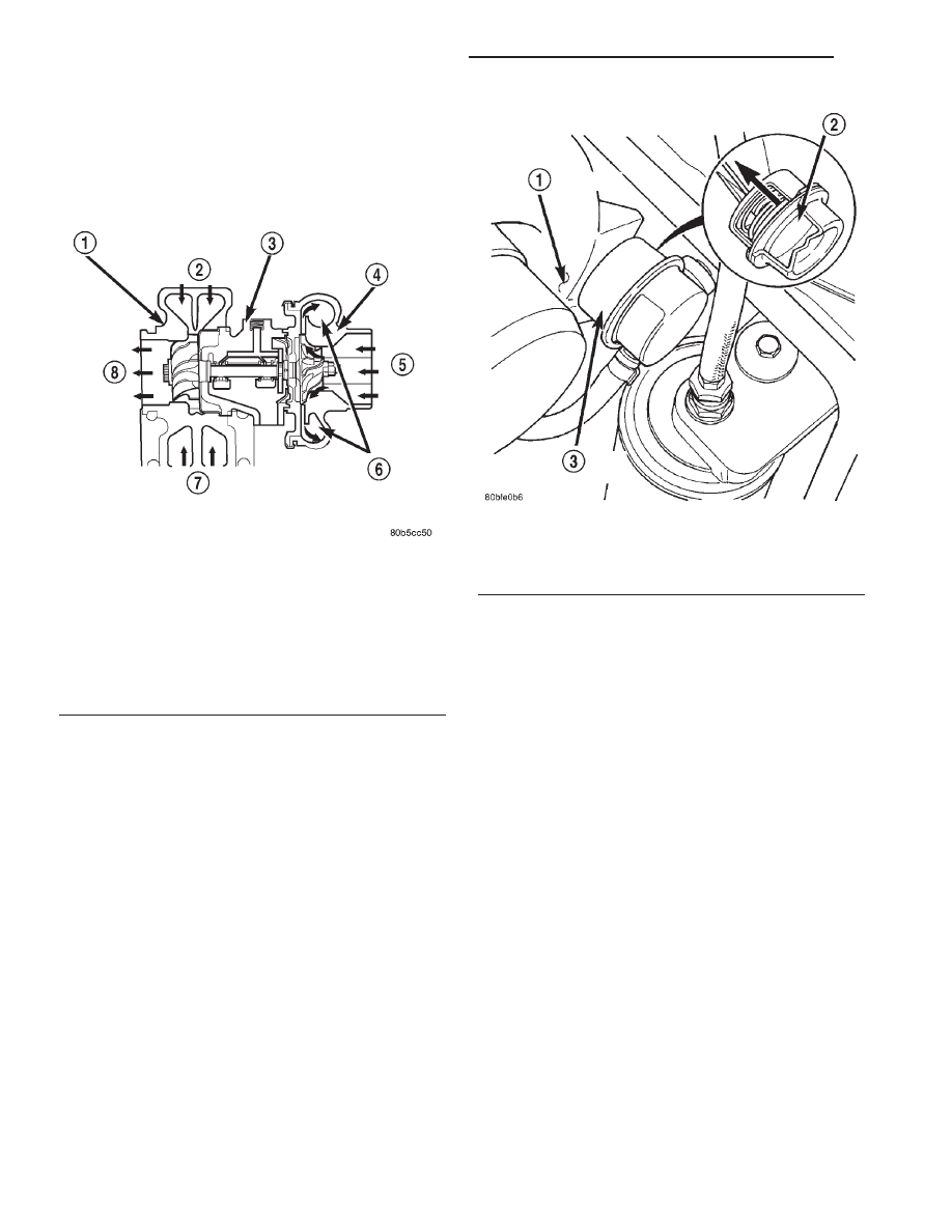
Fig. 1 Turbocharger Operation
1 - TURBINE SECTION
2 - EXHAUST GAS
3 - BEARING HOUSING
4 - COMPRESSOR SECTION
5 - INLET AIR
6 - COMPRESSED AIR TO ENGINE
7 - EXHAUST GAS
8 - EXHAUST GAS TO EXHAUST PIPE
Fig. 2 Turbocharger Wastegate Actuator
1 - TURBOCHARGER
2 - DIAPHRAM
3 - WASTE GATE ACTUATOR
11a - 2
EXHAUST SYSTEM AND TURBOCHARGER
R1
TURBOCHARGER SYSTEM (Continued)